ABOUT THIS 3D MODEL
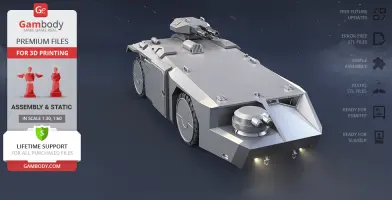
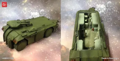
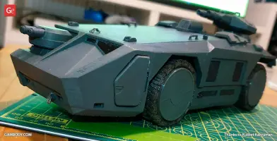
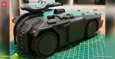
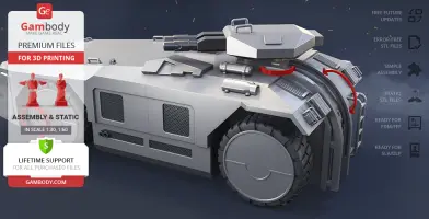
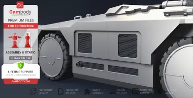
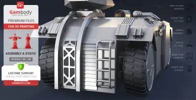
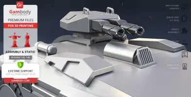
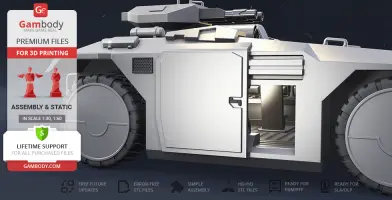
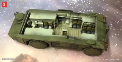
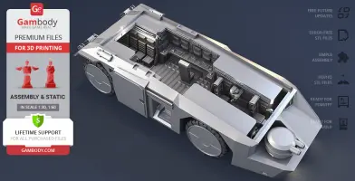
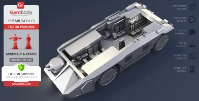
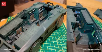
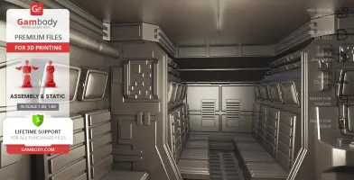
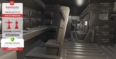
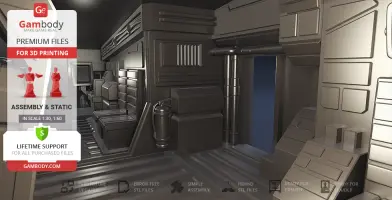
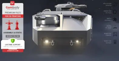
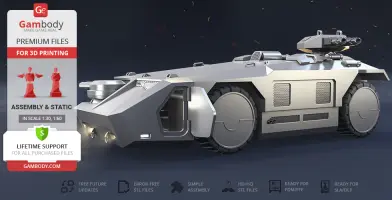
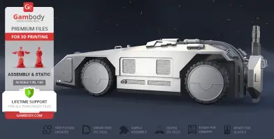
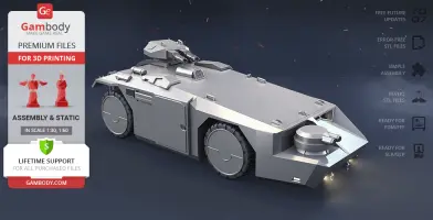
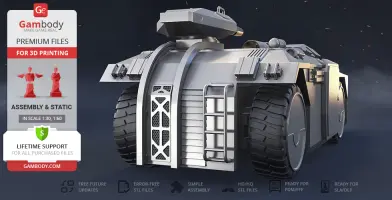
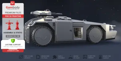
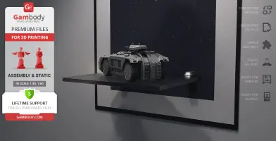
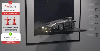
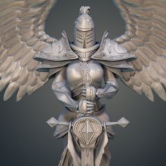
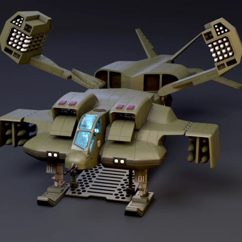
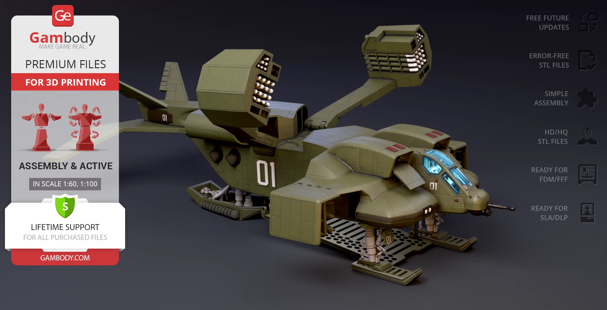
M577 Armoured Personnel Carrier, or simply APC, is an iconic troop transport of the Alien vs Predator franchise. Massive and lightweight at the same time, M577 first appeared in the 1986 Aliens film and subsequently was featured in various AvP video games and comic books. The author of the highly-detailed M577 model for 3D printing worked on the project circa 120 hours to make sure the awesome UD-4L Cheyenne Dropship has an actual troop transport to carry. The 3D artist equipped the vehicle with its full formidable arsenal of weaponry making M577 a very dangerous opponent to get close to. A pair of powerful and probably the vehicle’s trademark Republic Electric Gatling Cannons is positioned at the front of the carrier, ready to track and annihilate any extraterrestrial enemy! The roof-mounted turret also seems to be on high alert, offering 360-degree protection. Aside from the impressive exterior details that the tactical response vehicle boasts, the author of the model made sure to depict the passenger compartment of the M577 carrier as accurate as possible. It seems to lack only its 2+12 crew! M577 APC is well-loved by many Aliens fans and its design is considered to be truly iconic since it crossed over so many various media since the first appearance. Now the legendary carrier is ready to cover one more sphere and become a considerable member of your 3D printed autopark.
ADAPTATION FOR 3D PRINTING
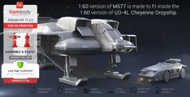
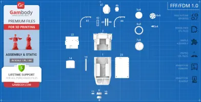
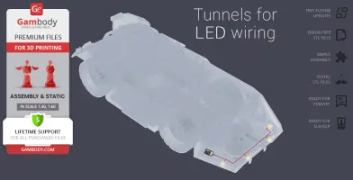
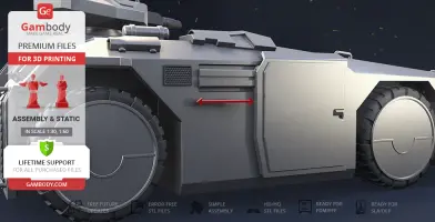
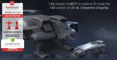
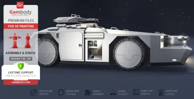
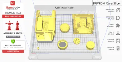
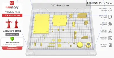
M577 Armoured Personnel Carrier 3D printing model is an assembly model and its moderation and adaptation for different types of 3D printers took Gambody team 38 hours in total. For you to receive the cleanest printing result possible and to minimise the amount of filament needed for generated support the vehicle model was divided into many assembly parts, e.g. top access ladder, access doors, cannons, cooling fins, brake lights, LED searchlight, missile launch bay cover etc. are provided as separate STL files. The driver main entry was made opening and the main side entry door is sliding for you to access the highly-detailed passenger compartment. Gatling cannon at the front of the carrier is poseable, as well as the roof turret, that it is mounted on a track to run down the rear of the APC for you to display the vehicle in a variety of scenarios. The windows on the driver compartment viewport are provided as two separate files to be printed with the transparent filament. The headlights and “parking lights” holes are made hollow for you to introduce LED wiring if willing. Moreover, the scale of the model’s DLP/SLA/SLS 1.0 version was chosen to fit inside the 1:60 UD-4L Cheyenne Dropship through its opening cargo door. All assembly parts are provided in STL files in recommended positions that were worked out in order to ensure the smoothness of the details’ surfaces after printing and that the 3D printing beginners won't face difficulties when placing the parts on a build plate. When downloading any model’s file you will also receive "Assembly Manual" for FFF/FDM 1.0 and DLP/SLA/SLS 1.0 versions in PDF format.
The model is saved in STL files, a format supported by most 3D printers. All STL files for 3D printing have been checked in Netfabb and no errors were shown.
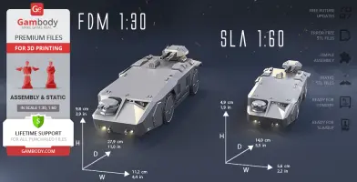
The model's scale was calculated from the length of the M577 APC that is 8580 mm. The 3D printing model's chosen scale is 1/30 for FFF/FDM version and 1/60 for DLP/SLA/SLS version.
VERSIONS' SPECIFICATIONS
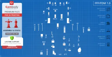
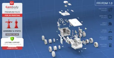
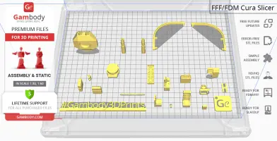
FFF/FDM 1.0 version features:
- Contains 69 parts;
- A printed model is 98 mm tall, 112 mm wide, 279 mm deep;
- Assembly kit includes lock 68_ge_lock_10_x9 to connect the parts securely without glue that needs to be printed 9 times;
- Windows on the driver compartment viewport are provided separately to be printed with the transparent filament for you to access the highly-detailed passenger compartment;
- Gatling cannon at the front of the APC is rotary; the roof turret is poseable as well and it is mounted on a track to run down the rear of the APC;
- Driver main entry is opening and the main side entry door is sliding;
- Two variants of wheels: a solid one for plastic filament and a separated to print the tyre with flexible material;
- All wheels are equipped with rotating gear bearings that are easily printed one-piece;
- All parts are divided in such a way that you will print them with the smallest number of support structures and so to ensure the smoothness of the details’ surfaces.
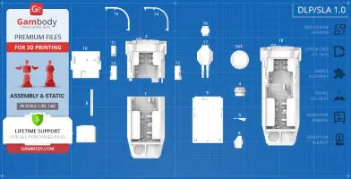
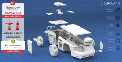
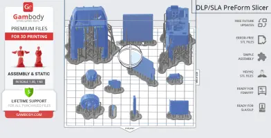
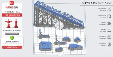
DLP/SLA/SLS 1.0 version features:
- Contains 17 parts;
- A printed model is 49 mm tall, 56 mm wide, 140 mm deep;
- The version's scale was chosen for the APC to fit into 1:60 version of UD-4L Cheyenne Dropship;
- Windows on the driver compartment viewport are provided separately to be printed with transparent material for you to access the highly-detailed passenger compartment;
- Gatling cannon at the front of the APC is rotary; the roof turret is poseable as well and it is mounted on a track to run down the rear of the APC;
- Driver main entry is opening and the main side entry door is sliding;
- All parts are divided in such a way to fit the build plates and to ensure that support structures are generated where needed.
WHAT WILL YOU GET AFTER PURCHASE?
- STL files of M577 Armoured Personnel Carrier 3D Printing Model which consist of 86 parts;
- 2 versions of files of this model for FFF/FDM and DLP/SLA/SLS printers;
- High-poly detailed model of M577 Armoured Personnel Carrier;
- Assembly Manual for FFF/FDM 1.0 and DLP/SLA/SLS 1.0 versions in PDF format;
- Detailed settings that we provide as a recommendation for Cura , Simplify3D and Slic3r for the best print;
- Full technical support from the Gambody Support Team.
You can get the model of M577 Armoured Personnel Carrier for 3D printing immediately after the purchase! Just click the green Buy button in the top-right corner of the model’s page. You can pay with PayPal or your credit card.
Watch the tutorial on how to assemble M577 Armoured Personnel Carrier 3D Printing Model at Gambody YouTube channel.
Also, you may like UD-4L Cheyenne Dropship 3D Printing Model as well as other Alien vs Predator 3D Printing Figurines.
_______
FAQ:
Where can I print a model if I have no printer?
How to get started with 3D printing?
How to set up my 3D printer?
How to choose right 3D model print bed positioning?
How to paint printed figurine?
Generic
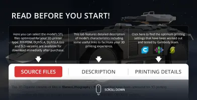
Below you can find printing recommendations for Cura, Simplify3D and Slic3r software.
These are basic settings that were tested in Cura 4.8.0 slicer.
The test models were printed on Ultimaker 2, Creality Ender 3, Creality CR-10S Pro V2, Anycubic I3 Mega, Anycubic I3 MegaS 3D printers with PLA and PETG filaments.
Disclaimer: The following printing settings are a recommendation, not an obligation. The parameters can vary depending on the peculiarities of your 3D printer, the material you use and especially the particular assembly part at hand. Each part that any model comprises often needs preliminary review and you are free to tweak the settings the way you find suitable.
Note:
- You can scale up the model (downscaling is not recommended!);
- All connectors should be printed at 100% Infill;
- For all parts of locks (“ge_lock” in “Source files”) you need to change "Brim" type to "Skirt" in Build Plate Adhesion section.
Quality
Layer Height: 0.12 mm (you can also set Layer Height at 0.16 or 0.2mm for 0.4mm nozzles)
Initial Layer Height: 0.2 mm (carefully level the print bed and keep your Initial Layer Height the same as the main Layer Height)
Line Width: 0.4 mm
Wall Line Width: 0.4 mm
Outer Wall Line Width: 0.4 mm
Inner Wall(s) Line Width: 0.4 mm
Top/Bottom Line Width: 0.4 mm
Infill Line Width: 0.4 mm
Skirt/Brim Line Width: 0.4 mm
Support Line Width: 0.4 mm
Initial Layer Line Width: 100%
Shell
Wall Thickness: 0.8 mm
Wall Line Count: 2
Outer Wall Wipe Distance: 0.3 mm
Top Surface Skin Layers: 0
Top/Bottom Thickness: 0.6 mm
Top Thickness: 0.6 mm
Top Layers: 5
Bottom Thickness: 0.6 mm
Bottom Layers: 5
Initial Bottom Layers: 5
Top/Bottom Pattern: Lines
Bottom Pattern Initial Layer: Lines
Top/Bottom Line Directions: [ ]
Outer Wall Inset: 0 mm
Optimize Wall Printing Order: Check
Compensate Wall Overlaps: Check
Compensate Inner Wall Overlaps: Check
Minimum Wall Flow: 0%
Fill Gaps Between Walls: Everywhere
Filter Out Tiny Gaps: Check
Horizontal Expansion: 0 mm
Initial Layer Horizontal Expansion: 0 mm
Hole horizontal expansion: 0
Z Seam Alignment: User Specified
Z Seam Position: Back
Z Seam X: Average length of your printer’s plate (e.g.”150” if your plate is 300mm on the X-axis)
Z Seam Y: A value higher than the length of your plate on the Y-axis (e.g. 700)
Seam Corner Preference: Hide Seam
Extra Skin Wall Count: 1
Skin Overlap Percentage: 10%
Skin Overlap 0.04 mm
Infill
Infill Density: 20% (for all smaller parts and for all parts of connectors use 100% Infill)
Infill Pattern: Triangles
Connect Infill Lines: Check
Infill Line Directions: [ ]
Infill X Offset: 0 mm
Infill Y Offset: 0 mm
Infill Line Multiplier: 1
Extra Infill Wall Count: 0
Infill Overlap Percentage: 10-20%
Infill Overlap: 0.04 mm
Skin Overlap Percentage: 5%
Skin Overlap: 0.02 mm
Infill Wipe Distance: 0 mm
Infill Layer Thickness: 0.24 mm
Gradual Infill Steps: 0
Infill Before Walls: Check
Minimum Infill Area: 0 mm2
Skin Removal Width: 0.8 mm
Top Skin Removal Width: 0.8 mm
Bottom Skin Removal Width: 0.8 mm
Skin Expand Distance: 0.8
Top Skin Expand Distance: 0.8
Bottom Skin Expand Distance: 0.8
Maximum Skin Angle for Expansion: 90˚
Minimum Skin Width for Expansion: 0.0
Skin Edge Support Thickness: 0
Skin Edge Support Layers: 0
Material
Initial Layer Flow: 100%
Printing Temperature: See your filament settings
Initial Printing Temperature: Your filament settings
Final Printing Temperature: Your filament settings
Build Plate Temperature: Your filament settings
Build Plate Temperature Initial Layer: Your filament settings + 5°
Flow: 100% (Important! If you face difficulty printing the model, you may need to adjust the Flow parameter. You may research the topic using the Internet or seek assistance at our Customer Support Team at support@gambody.com)
Speed
You can increase the printing Speed by 20% when you print simple objects. For small/thin parts you need to decrease the Speed by 25% - 50%.
Print Speed: 50 mm/s
Infill Speed: 50 mm/s
Wall Speed: 25 mm/s
Outer Wall Speed:25 mm/s
Inner Wall Speed: 50 mm/s
Top/Bottom Speed: 25mm/s
Support Speed: 25 mm/s
Support Infill Speed: 45 mm/s
Support Interface Speed: 25 mm/s
Support Roof Speed: 25 mm/s
Support Floor Speed: 25 mm/s
Travel Speed: 80 mm/s
Initial Layer Speed: 80 mm/s
Initial Layer Print Speed: 20 mm/s
Initial Layer Travel Speed: 80 mm/s
Skirt/Brim Speed: 20 mm/s
Z Hop Speed: 5 mm/s
Number of Slower Layers: 2
Enable Acceleration Control: Check
When printing simple objects, you need to set all Acceleration parameters at 500 mm/s. For small/thin parts you need to decrease the Acceleration by 50% - 70%.
Travel
Enable Retraction: Check
Retraction Distance: 4-8 mm, 1-3 mm for Direct Extruder (This is the most important retraction parameter. You can find your optimal value of Retraction Distance by printing any test object, e.g. bridges, towers etc.)
Retraction Speed: 25mm/s
Retraction Retract Speed: 25 mm/s
Retraction Prime Speed: 25 mm/s
Retraction Extra Prime Amount: 0 mm3
Retraction Minimum Travel: 1.5 mm
Maximum Retraction Count: 100
Minimum Extrusion Distance Window: 6,5 - 10 mm
Limit Support Retractions: Check
Combing Mode: All
Max Comb Distance With No Retract: 30 mm
Retract Before Outer Wall: Check
Avoid Printed Parts When Travelling: Check
Avoid Supports When Travelling: Check
Travel Avoid Distance: 1 mm
Layer Start X: 0.0 mm
Layer Start Y: 0.0 mm
Z Hop When Retracted: Check
Z Hop Height: 0,3 mm
Cooling
Enable Print Cooling: Check
Fan Speed: 100%
Regular Fan Speed: 100%
Maximum Fan Speed: 100%
Regular/Maximum Fan Speed Threshold: 10 s
Initial Fan Speed: 0%
Regular Fan Speed at Height: 0.36 mm
Regular Fan Speed at Layer: 3
Minimum Layer Time: 10 s
Minimum Speed: 10 mm/s
Support
Generate Support: Check
Support Structure: Normal (you can try using Tree Support Structure if you have difficulty printing any particular assembly part)
Support Placement: Everywhere
Support Overhang Angle: 60° (this parameter can range from 30° to 70° depending on the part at hand)
Support Pattern: Zig Zag
Support Wall Line Count: 1 (stronger support that might be more difficult to remove) 0 (less strong support but is easier to remove)
Support Density: 15%
Support Line Distance: 2.6667 mm
Initial layer support line distance: 2.667 mm
Support Z Distance: 0.12 mm
Support Top Distance: 0.12 mm
Support Bottom Distance: 0.12 mm
Support X/Y Distance: 0.8-1 mm
Support Distance Priority: Z overrides X/Y
Support Stair Step Height: 0.3 mm
Support Stair Step Maximum Width: 5.0 mm
Support Stair Step Minimum Slope Angle: 10°
Support Join Distance: 2.0 mm
Support Horizontal Expansion: 0.2 mm
Support Infill Layer Thickness: 0.2 mm
Gradual Support Infill Steps: 0
Minimum Support Area: 2 mm
Enable Support Interface: Check (generates additional “pillow” on the support structure that leads to a more even surface, but can be difficult to remove in hard-to-reach areas)
Enable Support Roof: Check
Enable Support Floor: Check
Support Interface Thickness: 0.8 mm
Support Roof Thickness: 0.8 mm
Support Floor Thickness: 0.8 mm
Support Interface Resolution 0.2 mm
Support Interface Density: 50-100%
Support Roof Density: 50-100%
Support Roof Line Distance: 0.8 mm
Support Floor Density: 50-100%
Support Floor line Distance: 0.4mm
Support Interface Pattern: Grid
Support Roof Pattern: Grid (this parameter should differ from Bottom Pattern Initial Layer in “Shell” section)
Support Floor Pattern: Grid
Minimum Support Interface Area: 10mm
Minimum Support Roof Area: 10 mm
Minimum Support Floor Area: 10 mm
Support Interface Horizontal Expansion: 0.0 mm
Support Roof Horizontal Expansion: 0.0 mm
Support Floor Horizontal Expansion: 0.0 mm
Fan Speed Override: Check
Supported Skin Fan Speed: 100%
Use Towers: Check
Tower Diameter: 4 mm
Minimum Diameter: 3.0 mm
Tower Roof Angle: 65°
Build Plate Adhesion
Build Plate Adhesion Type: Skirt/Brim (For unsteady parts, and those parts that may come unstuck use “Brim”. For bigger assembly parts that have large adhesion area and for all parts of locks and claws that you want to come out clean use "Skirt")
Skirt/Brim Minimum Length: 250 mm
Brim Width: 8.0 mm
Brim Line Count: 10
Brim Only on Outside: Check
Mesh Fixes
Union Overlapping Volumes: Check
Merged Meshes Overlap: 0.15 mm
Special Modes
Print Sequence: All at Once
Surface Mode: Normal
Experimental
Slicing Tolerance: Middle
Maximum Resolution: 0.01 mm
Flow rate compensation max extrusion offset: 0 mm
Flow rate compensation factor: 100%
This model was tested with PLA material.
To avoid printing problems, we recommend the following settings:
Extruder
Nozzle Diameter: 0.4 mm
Extrusion Multiplier: 0.97
Extrusion Width: Auto
Retraction Distance: 5.00 mm
Extra Restart Distance: 0.00 mm
Retraction Vertical Lift: 0.08 mm
Retraction Speed: 5400.0 mm/min
Wipe Distance: 5.00 mm
Layer
Primary Layer Height: 0.2 mm
Top Solid Layers: 8
Bottom Solid Layers: 5
Outline/Perimeter Shells: 2
Outline Direction: Inside-Out
First Layer Height: 90%
First Layer Width: 100%
First Layer Speed: 20%
Additions
Use Skirt/Brim: Check
Skirt Layers: 1
Skirt Offset from Part: 6.00 mm
Skirt Outlines: 5
Infill
Internal Fill Pattern: Fast Honeycomb
External Fill Patern: Rectilinear
Interior Fill Percentage: 10%
Outline Overlap: 22%
Infill Extrusion Width: 100%
Minimum Infill Length: 5.00 mm
Combine Infill Every: 1 layers
External Infill Angle Offsets: 45/-45 deg
Support
Generate Support Material: Check
Support Infill Percentage: 15%
Extra Inflation Distance: 1.00 mm
Support Base Layers: 0
Combine Support Every: 1 layers
Dense Support Layers: 0
Dense Infill Percentage: 70%
Support Type: Normal
Support Pillar Resolution: 5.00 mm
Max Overhang Angle: 60 deg
Horizontal Offset From Part: 0.50 mm
Upper Vertical Separation Layers: 1
Lower Vertical Separation Layers: 1
Support Infill Angles: 45 deg
Temperature
Extruder 1 Temperature: 210
Heated Bed: 60
Cooling
Increase fan speed for layers below: 45.0 sec
Maximum Cooling fan speed: 50%
Bridging fan speed override: 100%
Speeds
Default Printing Speed: 4800.0 mm/min
Outline Underspeed: 50%
Solid Infill Underspeed: 80%
Support Structure Underspeed: 80%
X/Y Axis Movement Speed: 10800.0 mm/min
Z Axis Movemen Speed: 1002.0 mm/min
Adjust printing speed for layers below: 15.0 sec
Allow speed reduction down to: 20%
Other
Unsupported area threshold: 20.0 sq m
Layer height
Layer height: 0.1 mm
First layer height: 90%
Vertical shells
Perimeters: 2
Horizontal shells
Soid layers:
Top: 8
Bottom: 5
Quality
Detect thin walls: Check
Detect bridging perimeters: Check
Advanced
Seam position: Random
Infill
Fill desity: 20%
Fill pattern: Honeycomb
Top/bottom fill pattern: Rectilinear
Reducing printing time
Combine infill every: 1 layers
Advanced
Solid infill every: 0 layers
Fill angle: 25 deg
Solid infill threshold area: 0mm
Skirt
Loops: 2
Distance from object: 6 mm
Skirt height: 1 layers
Minimum extrusion length: 4 mm
Brim
Brim width: 10 mm
Support material
Generate support material: Check
Overhang threshold: 45 deg
Enforce support for the first: 3 layers
Raft
Raft layers: 0 layers
Options for support material and raft
Contact Z distance: 0.1 mm
Pattern: Rectilinear
Patter spacing: 2 mm
Pattern angle: 0 deg
Interface layers: 2 layers
Interface pattern spacing: 0.2 mm
Speed for print moves
Perimeters: 60 mm/s
Small perimeters: 20 mm/s
External perimeters: 20 mm/s
Infill: 60 mm/s
Solid infill: 60 mm/s
Top solid infill: 30 mm/s
Support material: 50 mm/s
Support material interface: 100%
Bridges: 30 mm/s
Gap fill: 50 mm/s
Speed for non-print moves
Travel: 60 mm/s
Modifiers
First layer speed: 30 mm/s
Acceleration control
Perimeters: 800 mm/s
Infill: 1500 mm/s
Bridge: 1000 mm/s
First layer: 1000 mm/s
Default: 1000 mm/s
Autospeed
Max print speed: 100 mm/s
Max volumetrix speed: 0 mm/s
Extrusion width
Default extrusion width: 0.42 mm
First layer: 0.42 mm
Perimeters: 0.42 mm
External perimeters: 0.42 mm
Infill: 0.42 mm
Solid infill: 0.42 mm
Top solid infill: 0.42 mm
Support material: 0.42 mm
Overlap
Infill/Perimeters overlap: 20%
Flow
Bridge flow ratio: 0.95
Other
XY Size Compensation: 0 mm
Threds: 8
Resolution: 0 mm


Comments