This 3D Model consists of files in StereoLithography (.Stl) format that have been optimized for 3D printing.
Before printing the files, we strongly recommend reading the PRINTING DETAILS section.
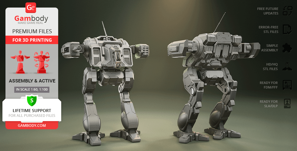
MWO Omega 3D Printing Model comes in 4 versions for each 3D printer type (FFF/FDM, DLP/SLA/SLS). Files for each version are available for download after the purchase.
Detailed information about this model is available in the DESCRIPTION section.
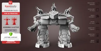
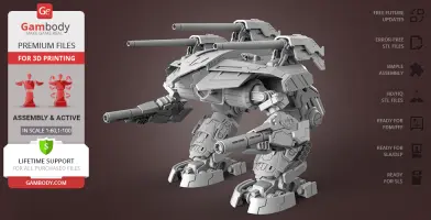
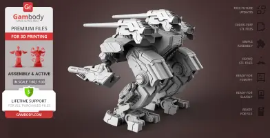
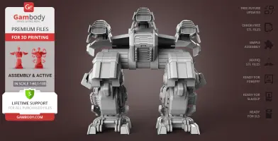
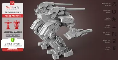
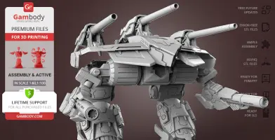
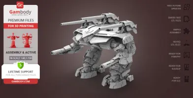
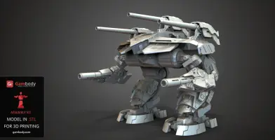
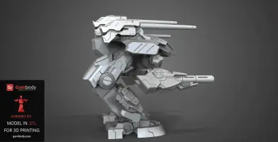
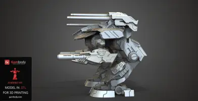
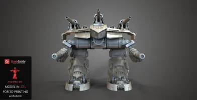
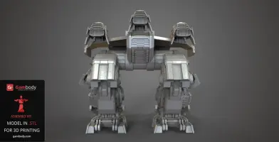
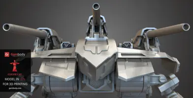
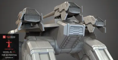
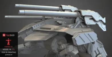
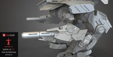
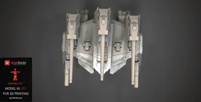
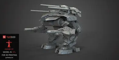
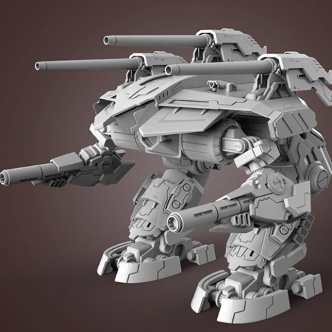
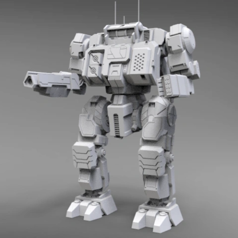
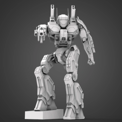
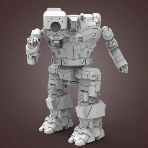
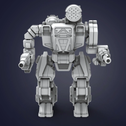
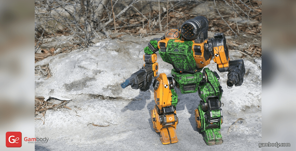
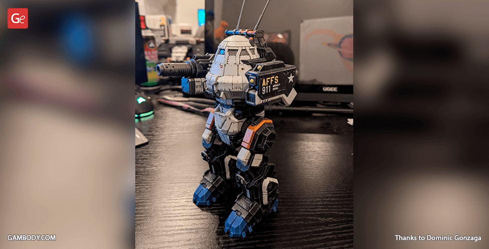
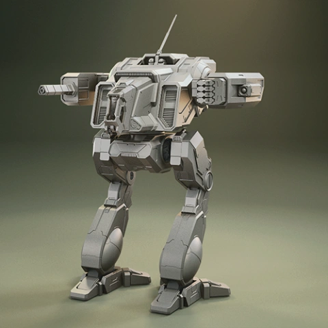
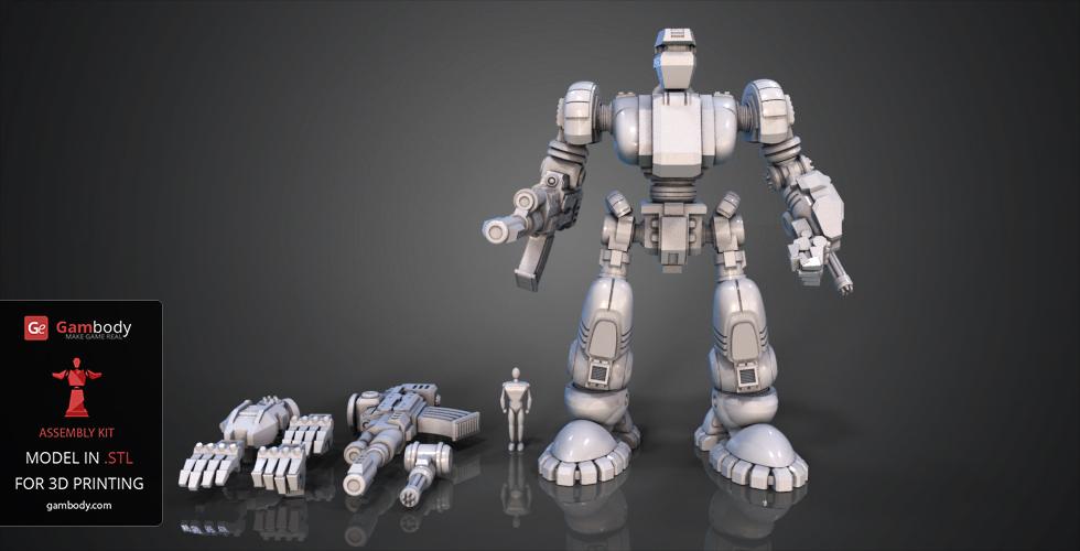
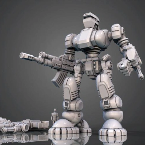
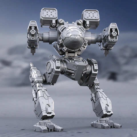
Omega BattleMech 3D model is inspired by the bulky Mech machine from the BattleTech universe. It is classified as a super-heavy BattleMech, due to its bulkier skeleton, one that hasn’t been designed before it. Capable of weathering huge amounts of fire and its weaponry made it a ruthless defence unit and an anti-aircraft platform.
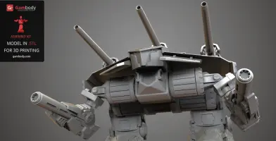
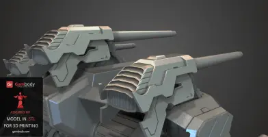
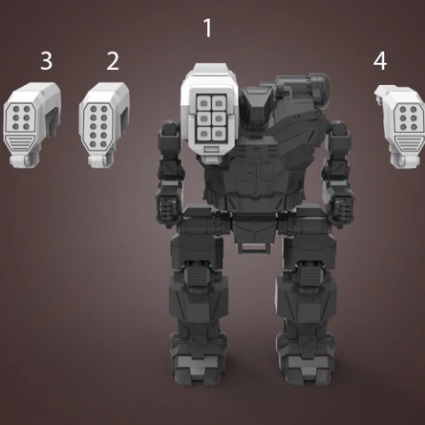
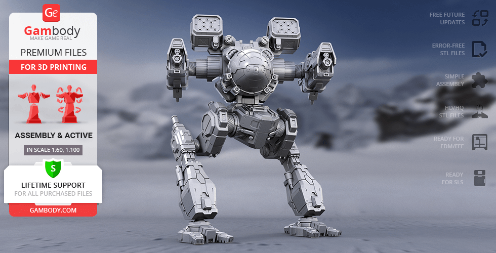
At its 150 tons mass, the Omega BattleMech can develop a speed of 32 km/h. Its signature design is the three M-7 Gauss Rifles mounted in each of the three torso areas.
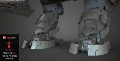
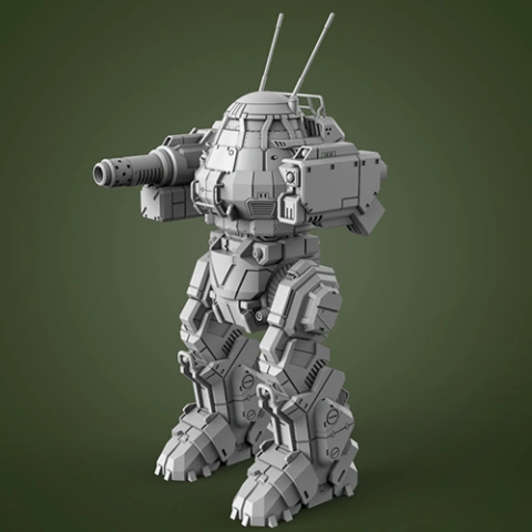
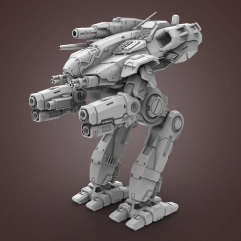
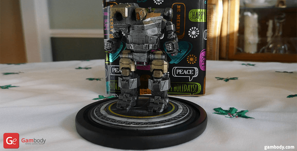
The Omega BattleMech 3D model features the video game prototype design lines. It features a bulky torso and the three Gauss Rifles. It is poseable figure, with complete workable feet. The improved joint design ensures full operability of the feet.
The 3D model STL files have been created in Autodesk Maya 3D modeling program. Every file has undergone complete checkup and correction in Netfabb and is error-free.
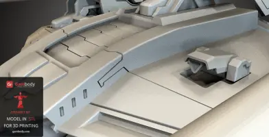
It is a high-poly 3D model with fine surface detailing and accurate printing details.
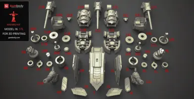
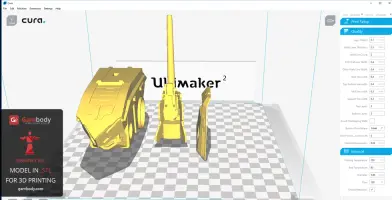
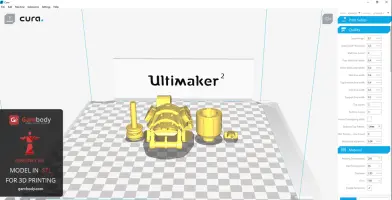
The Omega BattleMech 3D model consists of 44 parts. Every part is designed to fit on 18x19cm print bed and is converted into STL file format. The files can easily be handled in any slicing program, such as Cura 15.06 or Simplify3D.
Size of 3D printing Omega BattleMech 3D model
There are two scale versions for the 3D model:
FFF/FDM 1.1 is scaled at 188 mm x 174 mm x 171 mm.
FFF/FDM 1.0 - 213 mm x 230 mm x 210 mm.
Buy Omega BattleMech 3D model by clicking the green “Buy” button. Proceed to checkout. Insert your PayPal account or credit card details. Download the STL files and print them on your home 3D printer.
Note: If you don’t own a 3D printer, you can use 3DHubs 3D printing service to print your model. It’s easy. Just click the Print with 3DHubs button and you will be redirected to their website, where you can enter your location and look for 3D printing services and providers that are available in your city of residence.
________________________
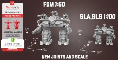
On 01.08.2018 new scale and new version of joints have been added.
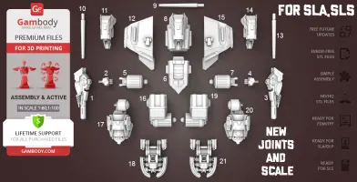
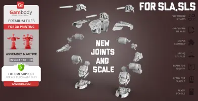
Now, the MWO Omega 3D Model is available in two scale: 1/60 for Version 2 (FFF/FDM) and 1/100 for Version 3 (DLP/SLA/SLS).
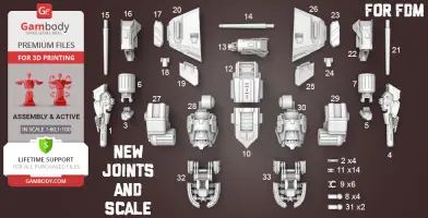
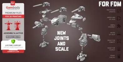
There are 33 parts in FFF/FDM 2.0 Version and 21 parts for DLP/SLA/SLS 1.0 Version
Was added parts of Locks, Connectors, and Joints for better fixing.
- One part of Lock (11_Ge_lock_10H_(x14)) you need to print 14 times.- One part of Connector (2_GE_Connector_C_D_(x4)) you need to print 4 times.- One part of Axis Joint (8_Axis_2_C_Joint_(x4)) you need to print 4 times.- One part of Claw (9_C_Claw_(x6)) you need to print 6 times.- One part of Axis Joint (31_Axis_1_C_Joint_(x2)) you need to print twice.
FFF/FDM 2.0:- Is 1:60 scale and after being printed will stand 300 mm tall, 330 mm wide, 305 mm deep;- Made with new joints;- All movable elements of the Mech were saved.
DLP/SLA/SLS 1.0:- Is 1:100 scale and will stand 180 mm tall, 198 mm wide, 183 mm deep;- Made with new joints;- All movable elements of the Mech were saved;- Has as few details as possible to keep printing costs down.
With new joints from Version 3 and Version 4 you will get next advantages:1. Increases frictional force;2. Possible to up scale or down scale the whole model;3. Printable from any type of material;4. Higher strength;5. Material shrinkage does not affect at strength and friction.
STL files with new scale and new joints are already available for download in “Source files” tab for:- FDM/FFF 2.0 Version;- DLP/SLA/SLS 1.0 Version.
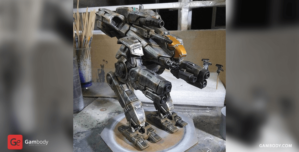
Watch the tutorial video on how to assemble Omega MWO 3D Printing Miniature at Gambody YouTube channel.
Also, you may like other Mechs from MWO universe.
______________
FAQ: Where can I print a model if I have no printer?How to get started with 3D printing?How to set up my 3D printer?How to choose right 3D model print bed positioning? How to paint printed figurine?
Generic
This model was tested in Cura 3.4.1 and printed on an Ultimaker 2 in PLA material.
Note:
- For parts of Locks and Claws you need to change "Brim" type to "Skirt" in Build Plate Adhesion section.
- You can print new joints with 20-30% infill.
- With the new joints you can up scale or down scale the whole model.
- You should print old joints with 100% infill.
- With the old joints do not try to up scale or down scale the whole model since it will not be assemble or movable after scale changes.
- Using the PLA material you should increase the scale of old joints at 2-3% in your slicing program.
- Using the ABS/CPE material you should increase the scale of old joints at 1% in your slicing program.
Recommendations: For all parts of Locks and Claws you need to change "Brim" type to "Skirt" in Build Plate Adhesion section.
To avoid printing problems, we recommend the following settings:
Quality
Layer Height: 0.1 mm
Initial Layer Height: 0.3 mm
Line Width: 0.4 mm
Wall Line Width: 0.4 mm
Outer Wall Line Width: 0.4 mm
Inner Wall(s) Line Width: 0.4 mm
Top/Bottom Line Width: 0.4 mm
Infill Line Width: 0.4 mm
Skirt/Brim Line Width: 0.4 mm
Support Line Width: 0.4 mm
Initial Layer Line Width: 100%
Shell
Wall Thickness: 0.8 mm
Wall Line Count: 2
Outer Wall Wipe Distance: 0.2 mm
Top Surface Skin Layers: 0
Top/Bottom Thickness: 0.8 mm
Top Thickness: 0.8 mm
Top Layers: 8
Bottom Thickness: 0.8 mm
Bottom Layers: 8
Top/Bottom Pattern: Lines
Bottom Pattern Initial Layer: Lines
Top/Bottom Line Directions: [ ]
Outer Wall Inset: 0 mm
Compensate Wall Overlaps: Check
Compensate Outer Wall Overlaps: Check
Compensate Inner Wall Overlaps: Check
Fill Gaps Between Walls: Everywhere
Filter Out Tiny Gaps: Check
Horizontal Expansion: 0 mm
Initial Layer Horizontal Expansion: 0 mm
Z Seam Alignment: Sharpest Corner
Seam Corner Preference: Hide Seam
Ignore Small Z Gaps: Check
Extra Skin Wall Count: 1
Infill
Infill Density: 20% (for all parts of connectors use 100% infill)
Infill Line Distance: 4.0 mm
Infill Pattern: Grid
Infill Line Directions: [ ]
Infill X Offset: 0 mm
Infill Y Offset: 0 mm
Infill Overlap Percentage: 10%
Infill Overlap: 0.04 mm
Skin Overlap Percentage: 5%
Skin Overlap: 0.02 mm
Infill Wipe Distance: 0.1 mm
Infill Layer Thickness: 0.1 mm
Gradual Infill Steps: 1
Gradual Infill Steps Height: 1.5 mm
Infill Before Walls: Check
Minimum Infill Area: 0 mm2
Skin Removal Width: 0.8 mm
Top Skin Removal Width: 0.8 mm
Bottom Skin Removal Width: 0.8 mm
Skin Expand Distance: 0.8
Top Skin Expand Distance: 0.8
Bottom Skin Expand Distance: 0.8
Maximum Skin Angle for Expansion: 90˚
Minimum Skin Width for Expansion: 0.0
Material
Initial Layer Flow: 100%
Enable Retraction: Check
Retraction Extra Prime Amount: 0 mm3
Retraction Minimum Travel: 0.8 mm
Maximum Retraction Count: 90
Minimum Extrusion Distance Window: 6.5 mm
Nozzle Switch Retraction Distance: 16 mm
Nozzle Switch Retraction Speed: 20 mm/s
Nozzle Switch Retract Speed: 20 mm/s
Nozzle Switch Prime Speed: 20 mm/s
Speed
Print Speed: 45 mm/s
Infill Speed: 50 mm/s
Wall Speed: 22.5 mm/s
Outer Wall Speed: 22.5 mm/s
Inner Wall Speed: 45 mm/s
Top/Bottom Speed: 15 mm/s
Travel Speed: 60 mm/s
Initial Layer Speed: 22.5 mm/s
Initial Layer Print Speed: 22.5 mm/s
Initial Layer Travel Speed: 30 mm/s
Skirt/Brim Speed: 30 mm/s
Maximum Z Speed: 0 mm/s
Number of Slower Layers: 2
Travel
Combing Mode: All
Avoid Printed Parts when Traveling: Check
Travel Avoid Distance: 0.625 mm
Layer Start X: 0.0 mm
Layer Start Y: 0.0 mm
Cooling
Enable Print Cooling: Check
Fan Speed: 100%
Regular Fan Speed: 100%
Maximum Fan Speed: 100%
Regular/Maximum Fan Speed Threshold: 10 s
Initial Fan Speed: 0%
Regular Fan Speed at Height: 0.3 mm
Regular Fan Speed at Layer: 2
Minimum Layer Time: 5 s
Minimum Speed: 10 mm/s
Support
Generate Support: Check
Support Placement: Everywhere
Support Overhang Angle: 60°
Support Pattern: Zig Zag
Connect Support ZigZags: Check
Support Density: 15 %
Support Line Distance: 1.3333 mm
Support Z Distance: 0.3 mm
Support Top Distance: 0.3 mm
Support Bottom Distance: 0.3 mm
Support X/Y Distance: 1 mm
Support Distance Priority: Z overrides X/Y
Minimum Support X/Y Distance: 0.25 mm
Support Stair Step Height: 0.3 mm
Support Stair Step Maximum Width: 5.0 mm
Support Join Distance: 2.0 mm
Support Horizontal Expansion: 0.2 mm
Support Infill Layer Thickness: 0.1 mm
Gradual Support Infill Steps: 0
Use Towers: Check
Tower Diameter: 3.0 mm
Minimum Diameter: 3.0 mm
Tower Roof Angle: 65°
Build Plate Adhesion
Build Plate Adhesion Type: Brim (for all parts of Locks and Claws use "Skirt")
Skirt/Brim Minimum Length: 250 mm
Brim Width: 8.0 mm
Brim Line Count: 18
Brim Only on Outside: Check
Mesh Fixes
Union Overlapping Volumes: Check
Merged Meshes Overlap: 0.15 mm
Special Modes
Print Sequence: All at Once
Surface Mode: Normal
Experimental
Slicing Tolerance: Middle
Maximum Resolution: 0.01 mm
Flow rate compensation max extrusion offset: 0 mm
Flow rate compensation factor: 100%
Disclaimer: This model will look outstanding if printed on SLA/SLS 3D printer. The accuracy of the model printed on FFF printer can vary from the result shown in the pictures.
This model was tested with PLA material.
To avoid printing problems, we recommend the following settings:
Extruder
Nozzle Diameter: 0.4 mm
Extrusion Multiplier: 0.97
Extrusion Width: Auto
Retraction Distance: 5.00 mm
Extra Restart Distance: 0.00 mm
Retraction Vertical Lift: 0.08 mm
Retraction Speed: 5400.0 mm/min
Wipe Distance: 5.00 mm
Layer
Primary Layer Height: 0.2 mm
Top Solid Layers: 8
Bottom Solid Layers: 5
Outline/Perimeter Shells: 2
Outline Direction: Inside-Out
First Layer Height: 90%
First Layer Width: 100%
First Layer Speed: 20%
Additions
Use Skirt/Brim: Check
Skirt Layers: 1
Skirt Offset from Part: 6.00 mm
Skirt Outlines: 5
Infill
Internal Fill Pattern: Fast Honeycomb
External Fill Patern: Rectilinear
Interior Fill Percentage: 10%
Outline Overlap: 22%
Infill Extrusion Width: 100%
Minimum Infill Length: 5.00 mm
Combine Infill Every: 1 layers
External Infill Angle Offsets: 45/-45 deg
Support
Generate Support Material: Check
Support Infill Percentage: 15%
Extra Inflation Distance: 1.00 mm
Support Base Layers: 0
Combine Support Every: 1 layers
Dense Support Layers: 0
Dense Infill Percentage: 70%
Support Type: Normal
Support Pillar Resolution: 5.00 mm
Max Overhang Angle: 60 deg
Horizontal Offset From Part: 0.50 mm
Upper Vertical Separation Layers: 1
Lower Vertical Separation Layers: 1
Support Infill Angles: 45 deg
Temperature
Extruder 1 Temperature: 210
Heated Bed: 60
Cooling
Increase fan speed for layers below: 45.0 sec
Maximum Cooling fan speed: 50%
Bridging fan speed override: 100%
Speeds
Default Printing Speed: 4800.0 mm/min
Outline Underspeed: 50%
Solid Infill Underspeed: 80%
Support Structure Underspeed: 80%
X/Y Axis Movement Speed: 10800.0 mm/min
Z Axis Movemen Speed: 1002.0 mm/min
Adjust printing speed for layers below: 15.0 sec
Allow speed reduction down to: 20%
Other
Unsupported area threshold: 20.0 sq m


Comments