MWO Stalker Weapon Pack for 3D Printing | Assembly
4 Feedbacks
Images
general
Community 3D Prints
Video
Assembly guide
How it's made
360° Preview
Specifications
Source Files
Feedbacks (4)
Description
Printing Details
Update History
Comments
Specifications
Source Files
Feedbacks (4)
Description
Printing Details
Update History
Comments
MWO Stalker Weapon Pack for 3D Printing | Assembly
Specifications
Files
3D model format
Stereolithography (.stl)
Total files
44
The total number of 3D model files available across all versions and updates of this model, including variants optimized for different types of 3D printers.
License
Personal use
Slicer settings
not available
Mesh error check
not specified
Support
Lifetime support from Gambody team
Update requests
not specified
Model complexity
not specified
Assembly guide
Video
Model versions
1.0 Initial
FFF/FDM
Files
44
Parts
not specified
Scale
not specified
Printed model size
not specified
Printed base size
not specified
Assembly method
not specified
Features
not specified
Additional details
Part of diorama
No
Special pack included
No
You will get instant access to the STL files of MWO Stalker Weapon Pack for 3D Printing | Assembly after completing your purchase. Simply add the model to your cart and check out using PayPal, credit or debit card, Apple Pay, Google Pay, Alipay, or other available payment methods.
Watch the assembly video for MWO Stalker Weapon Pack for 3D Printing | Assembly, and explore more tutorials, behind-the-scenes content, 3D printing timelapses, and painting guides on the official Gambody YouTube channel.
Source Files
This Weapon Pack for 3D Printing consists of files in StereoLithography (.Stl) format that is optimized for 3D printing.
Before printing the files, we strongly recommend reading the PRINTING DETAILS section.
MWO Stalker Weapon Pack for 3D Printing comes in 1 version for FFF/FDM 3D printers. Files for 3D printing are available for download after the purchase.
Detailed information about this 3D printing model is available in the DESCRIPTION section.
Important
Before printing, take a look at Printing Details for recommended settings and tips to achieve better results.
--Select printer type--
FFF/FDM
Selected
The model is optimized for 3D printing on FFF/FDM printers using filament as the amount of support structures during printing and to ensure that each part fits on an average-sized print bed.
View update history
--Select model version--
1.0
Selected
Initial
File name
Size (mm | in)
Size(mb)
Printing Time / Filament
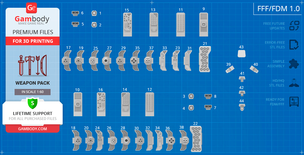
44_Gun_E_4_FDM(repaired).stl 11 x 25 x 10 mm | 0.43 x 0.98 x 0.39 in
Size: 11 x 25 x 10 mm | 0.43 x 0.98 x 0.39 in
File size: 0.34 mb
Printing Time / Filament: 14 min / <1 m
43_Gun_E_3_FDM(repaired).stl 14 x 13 x 7 mm | 0.55 x 0.51 x 0.28 in
Size: 14 x 13 x 7 mm | 0.55 x 0.51 x 0.28 in
File size: 0.02 mb
Printing Time / Filament: 11 min / <1 m
42_Gun_E_2_FDM(repaired).stl 11 x 26 x 12 mm | 0.43 x 1.02 x 0.47 in
Size: 11 x 26 x 12 mm | 0.43 x 1.02 x 0.47 in
File size: 0.24 mb
Printing Time / Filament: 18 min / <1 m
41_Gun_E_1_FDM(repaired).stl 11 x 23 x 10 mm | 0.43 x 0.91 x 0.39 in
Size: 11 x 23 x 10 mm | 0.43 x 0.91 x 0.39 in
File size: 0.20 mb
Printing Time / Filament: 13 min / <1 m
40_Gun_D_1_L_FDM(repaired).stl 7 x 32 x 8 mm | 0.28 x 1.26 x 0.31 in
Size: 7 x 32 x 8 mm | 0.28 x 1.26 x 0.31 in
File size: 0.05 mb
Printing Time / Filament: 12 min / <1 m
39_Gun_D_1_R_FDM(repaired).stl 7 x 32 x 8 mm | 0.28 x 1.26 x 0.31 in
Size: 7 x 32 x 8 mm | 0.28 x 1.26 x 0.31 in
File size: 0.05 mb
Printing Time / Filament: 12 min / <1 m
38_Gun_C_12_L_FDM (repaired).stl 17 x 36 x 45 mm | 0.67 x 1.42 x 1.77 in
Size: 17 x 36 x 45 mm | 0.67 x 1.42 x 1.77 in
File size: 0.67 mb
Printing Time / Filament: 1 h / <1 m
37_Gun_C_12_R_FDM (repaired).stl 17 x 36 x 45 mm | 0.67 x 1.42 x 1.77 in
Size: 17 x 36 x 45 mm | 0.67 x 1.42 x 1.77 in
File size: 0.67 mb
Printing Time / Filament: 59 min / <1 m
36_Gun_C_11_L_FDM (repaired).stl 17 x 36 x 49 mm | 0.67 x 1.42 x 1.93 in
Size: 17 x 36 x 49 mm | 0.67 x 1.42 x 1.93 in
File size: 1.85 mb
Printing Time / Filament: 1 h 24 min / 1 m
35_Gun_C_10_R_FDM (repaired).stl 17 x 36 x 49 mm | 0.67 x 1.42 x 1.93 in
Size: 17 x 36 x 49 mm | 0.67 x 1.42 x 1.93 in
File size: 1.85 mb
Printing Time / Filament: 1 h 23 min / 1 m
34_Gun_C_9_L_FDM (repaired).stl 15 x 36 x 7 mm | 0.59 x 1.42 x 0.28 in
Size: 15 x 36 x 7 mm | 0.59 x 1.42 x 0.28 in
File size: 0.18 mb
Printing Time / Filament: 18 min / <1 m
33_Gun_C_9_R_FDM (repaired).stl 15 x 36 x 7 mm | 0.59 x 1.42 x 0.28 in
Size: 15 x 36 x 7 mm | 0.59 x 1.42 x 0.28 in
File size: 0.19 mb
Printing Time / Filament: 18 min / <1 m
32_Gun_C_8_L_FDM (repaired).stl 15 x 36 x 7 mm | 0.59 x 1.42 x 0.28 in
Size: 15 x 36 x 7 mm | 0.59 x 1.42 x 0.28 in
File size: 0.94 mb
Printing Time / Filament: 18 min / <1 m
31_Gun_C_8_R_FDM (repaired).stl 15 x 36 x 7 mm | 0.59 x 1.42 x 0.28 in
Size: 15 x 36 x 7 mm | 0.59 x 1.42 x 0.28 in
File size: 0.94 mb
Printing Time / Filament: 18 min / <1 m
30_Gun_C_7_L_FDM (repaired).stl 17 x 36 x 56 mm | 0.67 x 1.42 x 2.2 in
Size: 17 x 36 x 56 mm | 0.67 x 1.42 x 2.2 in
File size: 1.35 mb
Printing Time / Filament: 1 h 21 min / 1 m
29_Gun_C_7_R_FDM (repaired).stl 17 x 36 x 56 mm | 0.67 x 1.42 x 2.2 in
Size: 17 x 36 x 56 mm | 0.67 x 1.42 x 2.2 in
File size: 1.33 mb
Printing Time / Filament: 1 h 18 min / 1 m
28_Gun_C_6_L_FDM (repaired).stl 17 x 36 x 40 mm | 0.67 x 1.42 x 1.57 in
Size: 17 x 36 x 40 mm | 0.67 x 1.42 x 1.57 in
File size: 1.00 mb
Printing Time / Filament: 49 min / <1 m
27_Gun_C_6_R_FDM (repaired).stl 17 x 36 x 40 mm | 0.67 x 1.42 x 1.57 in
Size: 17 x 36 x 40 mm | 0.67 x 1.42 x 1.57 in
File size: 1.00 mb
Printing Time / Filament: 48 min / <1 m
26_Gun_C_5_L_FDM (repaired).stl 17 x 36 x 38 mm | 0.67 x 1.42 x 1.5 in
Size: 17 x 36 x 38 mm | 0.67 x 1.42 x 1.5 in
File size: 0.33 mb
Printing Time / Filament: 35 min / <1 m
25_Gun_C_5_R_FDM (repaired).stl 17 x 36 x 38 mm | 0.67 x 1.42 x 1.5 in
Size: 17 x 36 x 38 mm | 0.67 x 1.42 x 1.5 in
File size: 0.33 mb
Printing Time / Filament: 35 min / <1 m
24_Gun_C_4_L_FDM (repaired).stl 15 x 36 x 7 mm | 0.59 x 1.42 x 0.28 in
Size: 15 x 36 x 7 mm | 0.59 x 1.42 x 0.28 in
File size: 0.25 mb
Printing Time / Filament: 19 min / <1 m
23_Gun_C_4_R_FDM (repaired).stl 15 x 36 x 7 mm | 0.59 x 1.42 x 0.28 in
Size: 15 x 36 x 7 mm | 0.59 x 1.42 x 0.28 in
File size: 0.25 mb
Printing Time / Filament: 19 min / <1 m
22_Gun_C_3_L_FDM (repaired).stl 21 x 45 x 45 mm | 0.83 x 1.77 x 1.77 in
Size: 21 x 45 x 45 mm | 0.83 x 1.77 x 1.77 in
File size: 0.70 mb
Printing Time / Filament: 3 h 39 min / 2 m
21_Gun_C_3_R_FDM (repaired).stl 21 x 45 x 45 mm | 0.83 x 1.77 x 1.77 in
Size: 21 x 45 x 45 mm | 0.83 x 1.77 x 1.77 in
File size: 0.70 mb
Printing Time / Filament: 3 h 39 min / 2 m
20_Gun_C_2_L_FDM (repaired).stl 17 x 36 x 41 mm | 0.67 x 1.42 x 1.61 in
Size: 17 x 36 x 41 mm | 0.67 x 1.42 x 1.61 in
File size: 0.33 mb
Printing Time / Filament: 53 min / <1 m
19_Gun_C_2_R_FDM (repaired).stl 17 x 36 x 41 mm | 0.67 x 1.42 x 1.61 in
Size: 17 x 36 x 41 mm | 0.67 x 1.42 x 1.61 in
File size: 0.33 mb
Printing Time / Filament: 53 min / <1 m
18_Gun_C_1_L_FDM (repaired).stl 17 x 36 x 50 mm | 0.67 x 1.42 x 1.97 in
Size: 17 x 36 x 50 mm | 0.67 x 1.42 x 1.97 in
File size: 1.58 mb
Printing Time / Filament: 1 h 12 min / 1 m
17_Gun_C_1_R_FDM (repaired).stl 17 x 36 x 50 mm | 0.67 x 1.42 x 1.97 in
Size: 17 x 36 x 50 mm | 0.67 x 1.42 x 1.97 in
File size: 1.57 mb
Printing Time / Filament: 1 h 9 min / 1 m
16_Gun_B_4_L_FDM (repaired).stl 15 x 41 x 11 mm | 0.59 x 1.61 x 0.43 in
Size: 15 x 41 x 11 mm | 0.59 x 1.61 x 0.43 in
File size: 0.40 mb
Printing Time / Filament: 40 min / <1 m
15_Gun_B_4_R_FDM (repaired).stl 15 x 41 x 11 mm | 0.59 x 1.61 x 0.43 in
Size: 15 x 41 x 11 mm | 0.59 x 1.61 x 0.43 in
File size: 0.40 mb
Printing Time / Filament: 40 min / <1 m
14_Gun_B_3_L_FDM (repaired).stl 15 x 41 x 11 mm | 0.59 x 1.61 x 0.43 in
Size: 15 x 41 x 11 mm | 0.59 x 1.61 x 0.43 in
File size: 0.47 mb
Printing Time / Filament: 39 min / <1 m
13_Gun_B_3_R_FDM (repaired).stl 15 x 41 x 11 mm | 0.59 x 1.61 x 0.43 in
Size: 15 x 41 x 11 mm | 0.59 x 1.61 x 0.43 in
File size: 0.47 mb
Printing Time / Filament: 39 min / <1 m
12_Gun_B_2_L_FDM (repaired).stl 15 x 41 x 11 mm | 0.59 x 1.61 x 0.43 in
Size: 15 x 41 x 11 mm | 0.59 x 1.61 x 0.43 in
File size: 0.94 mb
Printing Time / Filament: 38 min / <1 m
11_Gun_B_2_R_FDM (repaired).stl 15 x 41 x 11 mm | 0.59 x 1.61 x 0.43 in
Size: 15 x 41 x 11 mm | 0.59 x 1.61 x 0.43 in
File size: 0.94 mb
Printing Time / Filament: 38 min / <1 m
10_Gun_B_1_L_FDM (repaired).stl 15 x 41 x 11 mm | 0.59 x 1.61 x 0.43 in
Size: 15 x 41 x 11 mm | 0.59 x 1.61 x 0.43 in
File size: 0.41 mb
Printing Time / Filament: 40 min / <1 m
9_Gun_B_1_R_FDM (repaired).stl 15 x 41 x 11 mm | 0.59 x 1.61 x 0.43 in
Size: 15 x 41 x 11 mm | 0.59 x 1.61 x 0.43 in
File size: 0.41 mb
Printing Time / Filament: 40 min / <1 m
8_Gun_A_3_L_FDM (repaired).stl 13 x 9 x 18 mm | 0.51 x 0.35 x 0.71 in
Size: 13 x 9 x 18 mm | 0.51 x 0.35 x 0.71 in
File size: 0.14 mb
Printing Time / Filament: 19 min / <1 m
7_Gun_A_4_L_FDM (repaired).stl 13 x 9 x 18 mm | 0.51 x 0.35 x 0.71 in
Size: 13 x 9 x 18 mm | 0.51 x 0.35 x 0.71 in
File size: 0.14 mb
Printing Time / Filament: 19 min / <1 m
6_Gun_A_3_R_FDM (repaired).stl 13 x 9 x 18 mm | 0.51 x 0.35 x 0.71 in
Size: 13 x 9 x 18 mm | 0.51 x 0.35 x 0.71 in
File size: 0.14 mb
Printing Time / Filament: 19 min / <1 m
5_Gun_A_4_R_FDM (repaired).stl 13 x 9 x 18 mm | 0.51 x 0.35 x 0.71 in
Size: 13 x 9 x 18 mm | 0.51 x 0.35 x 0.71 in
File size: 0.14 mb
Printing Time / Filament: 19 min / <1 m
4_Gun_A_2_L_FDM (repaired).stl 10 x 9 x 13 mm | 0.39 x 0.35 x 0.51 in
Size: 10 x 9 x 13 mm | 0.39 x 0.35 x 0.51 in
File size: 0.20 mb
Printing Time / Filament: 13 min / <1 m
3_Gun_A_1_L_FDM (repaired).stl 10 x 9 x 13 mm | 0.39 x 0.35 x 0.51 in
Size: 10 x 9 x 13 mm | 0.39 x 0.35 x 0.51 in
File size: 0.20 mb
Printing Time / Filament: 14 min / <1 m
2_Gun_A_2_R_FDM (repaired).stl 10 x 9 x 13 mm | 0.39 x 0.35 x 0.51 in
Size: 10 x 9 x 13 mm | 0.39 x 0.35 x 0.51 in
File size: 0.20 mb
Printing Time / Filament: 13 min / <1 m
1_Gun_A_1_R_FDM (repaired).stl 10 x 9 x 13 mm | 0.39 x 0.35 x 0.51 in
Size: 10 x 9 x 13 mm | 0.39 x 0.35 x 0.51 in
File size: 0.20 mb
Printing Time / Filament: 14 min / <1 m
Models are regularly enhanced with updates and adjustments based on customer feedback. View update history
Description
ABOUT THIS 3D MODEL
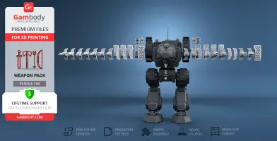
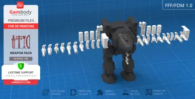
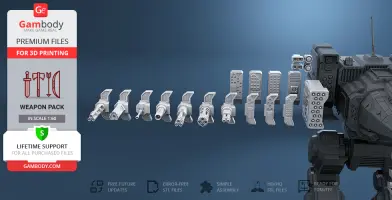
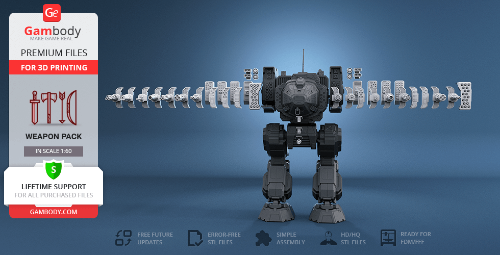
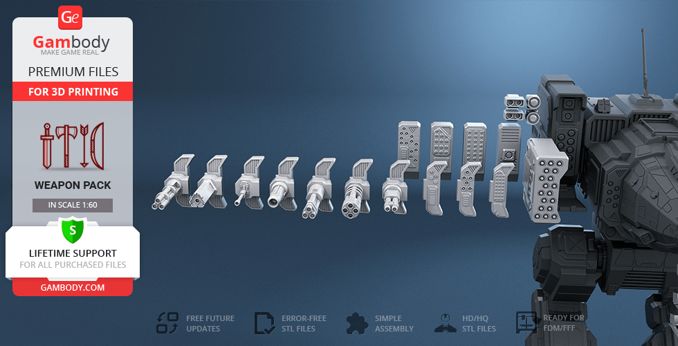
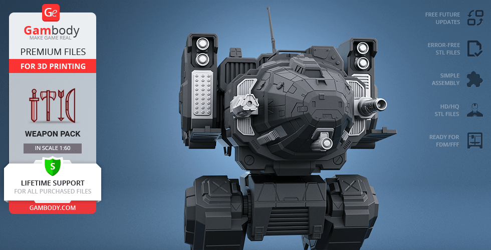
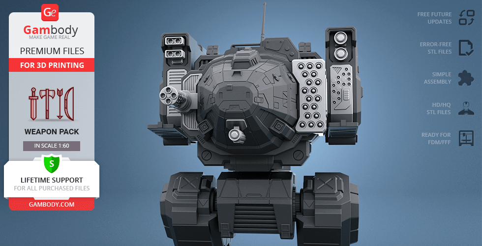
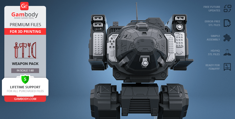
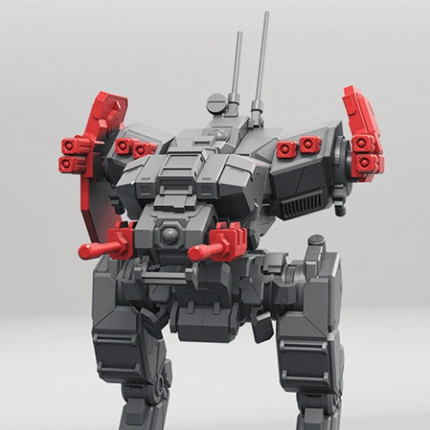
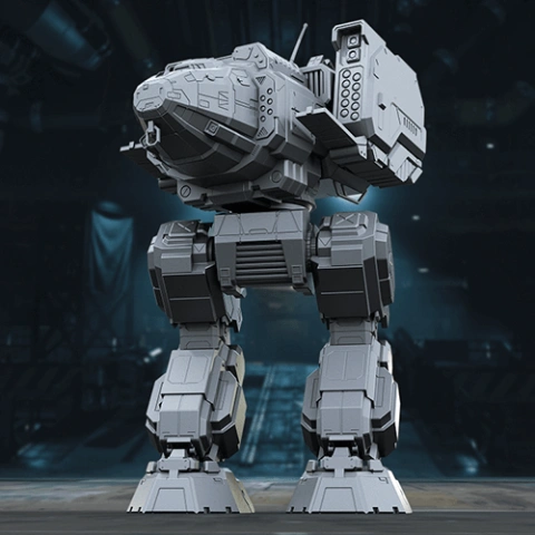
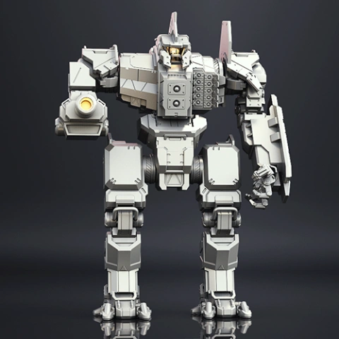
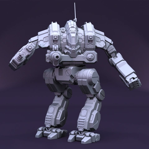
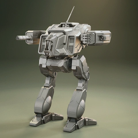
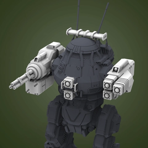
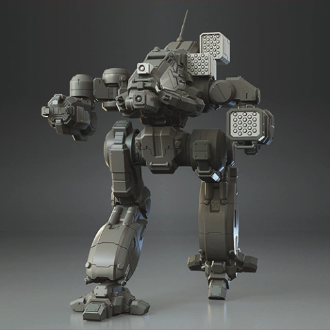
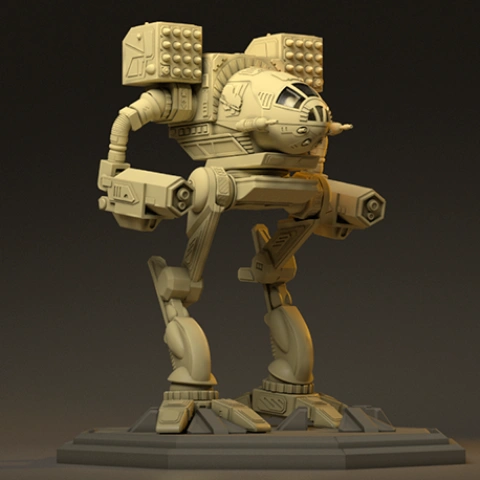
Looking for a powerful loadout to upgrade your 3D printed Stalker and set off for a new battle with your favourite variant of the assault Mech? We’ve got you covered with this Weapon Pack for 3D printing that is comprised of all kinds of energy, ballistic and missileweapons for you to create your most desirable Stalker build. Stalker is an assault-weight Mech that is known to come with an impressive number of predefined weapon hardpoint slots. These slots are specially designated locations where certain guns or equipment can be mounted. The author of the Stalker model spent 36 hours to select and design all the weapons you may need to assemble your perfect fighting machine with the best armament. Here is a full list of weapons array that comprises the pack and that you can equip your 3D printed Stalker Mech with: 1. Particle Projection Cannons (PPCs) 2. Flamers 3. Ultra AC/5, Ultra AC/10, AC/2, Rotary AC/2 4. Gauss Rifles 5. Streak SMR (Short Range Missiles) 6. Medium Range Missiles 7. Long-Range Missiles 8. Lasers 9. Tag 10. Snub-Nose PPC Make sure not to fire them all at once - the Mech’s heat sinks might not stand the overload! If you are looking for weapon packs to upgrade your other favourite BattleMechs, we recommend that you check our MWO collection for 3D printing.
ADAPTATION FOR 3D PRINTING
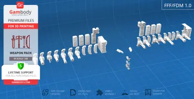
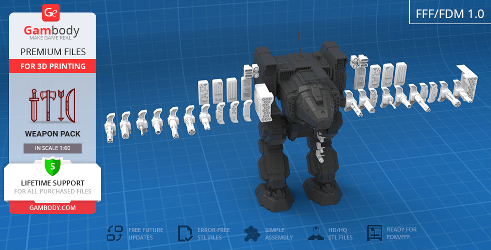
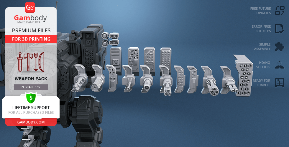
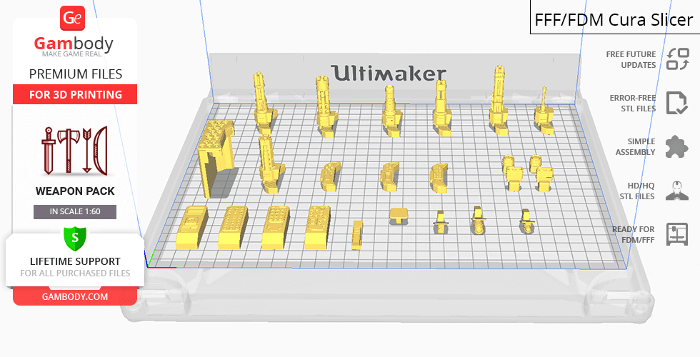
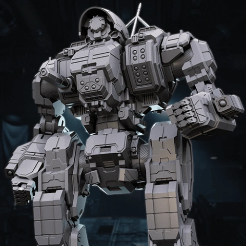
MWO Stalker Weapon Pack for 3D Printing is a set of weapons of different types that can be used to assemble various Stalker variants. The whole moderation process and adaptation of the weapon pack for different types of 3D printers took Gambody team 12 hours in total. Due to the design of the default loadout and hardpoints of the MWO Stalker, every initial gun the Mech is equipped with can easily be replaced with the respective weapon from the pack. During the moderation process, it was made sure that having printed the weapons that comprise the kit you will be able to easily insert them into the corresponding slots of the Stalker’s specially designed hardpoints. Every weapon in the pack comes in STL file in a recommended position that was worked out in order to ensure the smoothness of the detail’s surface after printing and so that 3D printing beginners won't face difficulties when placing the part on a build plate.
The model is saved in STL files, a format supported by most 3D printers. All STL files for 3D printing have been checked in Netfabb and no errors were shown.
The weapon's scale was calculated from Stalker's actual height that is 15800 mm. The 3D printing model's chosen scale is 1/60 for the FFF/FDM version.
VERSIONS' SPECIFICATIONS
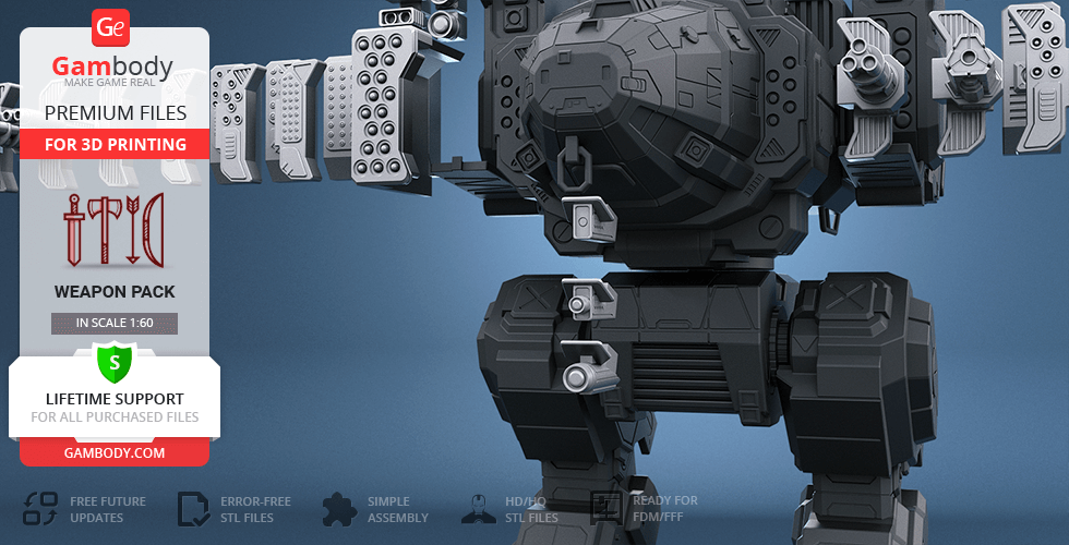
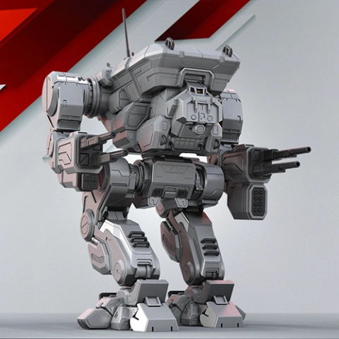
FFF/FDM 1.0 version features: - Contains 44 parts; - The pack is comprised of loadout weapon options to assemble the following Stalker variants: 1. STK-5M 2. STK-3F 3. STK-3H 4. STK-4N 5. STK-5S 6. STK-M 7. STK-3F(C) 8. STK-3FB - All parts are provided in STL files in recommended positions that were worked out in order to ensure the smoothness of the details’ surfaces after printing; - Once printed every weapon from the pack can be inserted into its designated place to modify the MWO Stalker 3D Printing Model.
WHAT WILL YOU GET AFTER PURCHASE?
- STL files of MWO Stalker Weapon Pack for 3D Printingwhich consist of 44 parts; - 1 version of files of this weapon pack for FFF/FDM printers; - High-poly detailed model of MWO Stalker Weapon Pack; - Detailed settings that we provide as a recommendation for Cura ,Simplify3D and Slic3r for the best print; - Full technical support from the Gambody Support Team.
You can get Weapon Pack for MWO Stalker for 3D Printing immediately after the purchase! Just click the green Buy button in the top-right corner of the model’s page. You can pay with PayPal or your credit card.
Quick rating from the old site version (no comment)
Overall experience
Level of detail in the model
3
Model cut quality and assembly guide
3
Clarity and accuracy of the model page
3
Reviewed on March 20, 2022
Verified purchase
User ID: 3773
Quick rating from the old site version (no comment)
Overall experience
Level of detail in the model
5
Model cut quality and assembly guide
5
Clarity and accuracy of the model page
5
Reviewed on January 07, 2020
This feedback is from a user who hasn't purchased this model
Aleksandr I.
Quick rating from the old site version (no comment)
Overall experience
Level of detail in the model
5
Model cut quality and assembly guide
5
Clarity and accuracy of the model page
5
Reviewed on January 02, 2020
This feedback is from a user who hasn't purchased this model
Gambody Support
Quick rating from the old site version (no comment)
Overall experience
Level of detail in the model
5
Model cut quality and assembly guide
5
Clarity and accuracy of the model page
5
Reviewed in United Kingdom of Great Britain and Northern Ireland on January 02, 2020
Community Support Team
Model rating
Overall experience
Level of detail in the model
Model cut quality and assembly guide
Clarity and accuracy of the model page
Enter for new line | Ctrl+Enter to submit text
Printing Details
Important
To avoid printing issues and achieve the best quality, we highly recommend applying the following settings:
Generic
This model was tested in Cura 3.4.1 and printed on an Ultimaker 2 in PLA material. Below you can find printing recommendations for Cura, Simplify3D and Slic3r softwares.
To avoid printing problems, we recommend the following settings:
Quality Layer Height: 0.1 mm Initial Layer Height: 0.3 mm Line Width: 0.4 mm Wall Line Width: 0.4 mm Outer Wall Line Width: 0.4 mm Inner Wall(s) Line Width: 0.4 mm Top/Bottom Line Width: 0.4 mm Infill Line Width: 0.4 mm Skirt/Brim Line Width: 0.4 mm Support Line Width: 0.4 mm Initial Layer Line Width: 100%
Shell Wall Thickness: 0.8 mm Wall Line Count: 2 Outer Wall Wipe Distance: 0.2 mm Top Surface Skin Layers: 0 Top/Bottom Thickness: 0.8 mm Top Thickness: 0.8 mm Top Layers: 8 Bottom Thickness: 0.8 mm Bottom Layers: 8 Top/Bottom Pattern: Lines Bottom Pattern Initial Layer: Lines Top/Bottom Line Directions: [ ] Outer Wall Inset: 0 mm Compensate Wall Overlaps: Check Compensate Outer Wall Overlaps: Check Compensate Inner Wall Overlaps: Check Fill Gaps Between Walls: Everywhere Filter Out Tiny Gaps: Check Horizontal Expansion: 0 mm Initial Layer Horizontal Expansion: 0 mm Z Seam Alignment: Sharpest Corner Seam Corner Preference: Hide Seam Ignore Small Z Gaps: Check Extra Skin Wall Count: 1
Infill Infill Density: 20% Infill Line Distance: 4.0 mm Infill Pattern: Grid Infill Line Directions: [ ] Infill X Offset: 0 mm Infill Y Offset: 0 mm Infill Overlap Percentage: 10% Infill Overlap: 0.04 mm Skin Overlap Percentage: 5% Skin Overlap: 0.02 mm Infill Wipe Distance: 0.1 mm Infill Layer Thickness: 0.1 mm Gradual Infill Steps: 1 Gradual Infill Steps Height: 1.5 mm Infill Before Walls: Check Minimum Infill Area: 0 mm2 Skin Removal Width: 0.8 mm Top Skin Removal Width: 0.8 mm Bottom Skin Removal Width: 0.8 mm Skin Expand Distance: 0.8 Top Skin Expand Distance: 0.8 Bottom Skin Expand Distance: 0.8 Maximum Skin Angle for Expansion: 90˚ Minimum Skin Width for Expansion: 0.0
Material Initial Layer Flow: 100% Enable Retraction: Check Retraction Extra Prime Amount: 0 mm3 Retraction Minimum Travel: 0.8 mm Maximum Retraction Count: 90 Minimum Extrusion Distance Window: 6.5 mm Nozzle Switch Retraction Distance: 16 mm Nozzle Switch Retraction Speed: 20 mm/s Nozzle Switch Retract Speed: 20 mm/s Nozzle Switch Prime Speed: 20 mm/s
Travel Combing Mode: All Avoid Printed Parts when Traveling: Check Travel Avoid Distance: 0.625 mm Layer Start X: 0.0 mm Layer Start Y: 0.0 mm
Cooling Enable Print Cooling: Check Fan Speed: 100% Regular Fan Speed: 100% Maximum Fan Speed: 100% Regular/Maximum Fan Speed Threshold: 10 s Initial Fan Speed: 0% Regular Fan Speed at Height: 0.3 mm Regular Fan Speed at Layer: 2 Minimum Layer Time: 5 s Minimum Speed: 10 mm/s
Support Generate Support: Check Support Placement: Everywhere Support Overhang Angle: 50° Support Pattern: Zig Zag Connect Support ZigZags: Check Support Density: 15 % Support Line Distance: 3 mm Support Z Distance: 0.1 mm Support Top Distance: 0.1 mm Support Bottom Distance: 0.1 mm Support X/Y Distance: 1 mm Support Distance Priority: Z overrides X/Y Minimum Support X/Y Distance: 0.25 mm Support Stair Step Height: 0.3 mm Support Stair Step Maximum Width: 5.0 mm Support Join Distance: 2.0 mm Support Horizontal Expansion: 0.2 mm Support Infill Layer Thickness: 0.1 mm Gradual Support Infill Steps: 0 Use Towers: Check Tower Diameter: 3.0 mm Minimum Diameter: 3.0 mm Tower Roof Angle: 65°
Build Plate Adhesion Build Plate Adhesion Type: Brim (for all parts of locks use "Skirt") Skirt/Brim Minimum Length: 250 mm Brim Width: 8.0 mm Brim Line Count: 18 Brim Only on Outside: Check
Mesh Fixes Union Overlapping Volumes: Check Merged Meshes Overlap: 0.15 mm
Special Modes Print Sequence: All at Once Surface Mode: Normal
Experimental Slicing Tolerance: Middle Maximum Resolution: 0.01 mm Flow rate compensation max extrusion offset: 0 mm Flow rate compensation factor: 100%
Disclaimer: This model will look outstanding if printed on SLA/SLS 3D printer. The accuracy of the model printed on FFF printer can vary from the result shown in the pictures.
To avoid printing problems, we recommend the following settings:
Extruder Nozzle Diameter: 0.4 mm Extrusion Multiplier: 0.97 Extrusion Width: Auto
Retraction Distance: 5.00 mm Extra Restart Distance: 0.00 mm Retraction Vertical Lift: 0.08 mm Retraction Speed: 5400.0 mm/min
Wipe Distance: 5.00 mm
Layer Primary Layer Height: 0.2 mm Top Solid Layers: 8 Bottom Solid Layers: 5 Outline/Perimeter Shells: 2 Outline Direction: Inside-Out
First Layer Height: 90% First Layer Width: 100% First Layer Speed: 20%
Additions Use Skirt/Brim: Check Skirt Layers: 1 Skirt Offset from Part: 6.00 mm Skirt Outlines: 5
Infill Internal Fill Pattern: Fast Honeycomb External Fill Patern: Rectilinear Interior Fill Percentage: 10% Outline Overlap: 22% Infill Extrusion Width: 100% Minimum Infill Length: 5.00 mm Combine Infill Every: 1 layers
External Infill Angle Offsets: 45/-45 deg
Support Generate Support Material: Check Support Infill Percentage: 15% Extra Inflation Distance: 1.00 mm Support Base Layers: 0 Combine Support Every: 1 layers
Dense Support Layers: 0 Dense Infill Percentage: 70%
Support Type: Normal Support Pillar Resolution: 5.00 mm Max Overhang Angle: 60 deg
Horizontal Offset From Part: 0.50 mm Upper Vertical Separation Layers: 1 Lower Vertical Separation Layers: 1
Support Infill Angles: 45 deg
Temperature Extruder 1 Temperature: 210 Heated Bed: 60
Cooling Increase fan speed for layers below: 45.0 sec Maximum Cooling fan speed: 50% Bridging fan speed override: 100%
Speeds Default Printing Speed: 4800.0 mm/min Outline Underspeed: 50% Solid Infill Underspeed: 80% Support Structure Underspeed: 80% X/Y Axis Movement Speed: 10800.0 mm/min Z Axis Movemen Speed: 1002.0 mm/min
Adjust printing speed for layers below: 15.0 sec Allow speed reduction down to: 20%
All 3D models on Gambody are sold as downloadable STL or OBJ files. These are digital assets created by 3D artists who are often inspired by characters, vehicles, and elements from popular franchises and universes. While these designs may resemble well-known works, they are original fan-made creations and not official merchandise. When purchasing a model, you are not buying the full ownership of the file or any associated intellectual property. Instead, you are receiving a license to use the digital files under specific terms, as defined by the model's creator. This is commonly referred to as a Digital File License (e.g., Standard, Extended, Creator), which outlines what you can and cannot do with both the files themselves and the 3D-printed objects made from them. Always check the license type to ensure it matches your intended use.
License: Personal use
SDFL
Selected
Standard Digital File License (SDFL) for hobby 3D printing and personal use only - no resale, file sharing, or commercial distribution of the files or printed models.
Files for each 3D model are prepared specifically for a certain 3D printing technology to ensure the best results. Selecting the correct printer type ensures you get files optimized for your machine - minimizing the risk of slicing issues, failed prints, or unnecessary supports. Each printer type (FFF/FDM, DLP/SLA, or SLS) uses different materials and has different printing capabilities, so it's important to choose the one that matches your actual 3D printer.
Printer type: All this model is optimized for
Selected
FFF/FDM
Selected
The model is optimized for 3D printing on FFF/FDM printers using filament as the amount
of support structures during printing and to ensure that each part fits on an average-sized print bed.
3D printing files for each model are organized into "model versions". These versions may vary by design quality (e.g., improved detailing), pose, outfit, or additional features. Some models may also offer special variations - such as ECO versions with hollowed parts for resin-saving prints. Before purchasing or downloading, choose the one that best fits your intended use - whether you re looking for the latest improved release or a specific variant tailored to your needs.
Model version: All current and future updates
Selected
Quality checked by Gambody
Lifetime support from Gambody
Sale -33%
9.99 USD
6.69 USD
Black Wolf
3D Artist
(84)
Author rating is the average of all customer ratings from feedback left on this creator's models.
Followers: 11
Response: 100% · Avg. reply: 24h
Achievements
Achievements are coming soon - stay tuned for future updates!
We're glad you're here! Before you continue, let's set a few preferences to improve your experience on our marketplace. By clicking "Accept", you agree to our use of cookies to make your visit more enjoyable and personalized. This helps us offer you tailored product recommendations and relevant marketing content. Enjoy your time with Gambody, and thank you for choosing us!
Customise Consent Preferences
When you visit any website, it may collect and store information through cookies. These small data files help understand your preferences and improve your overall experience. While they usually don't identify you directly, they make your web experience more personalized. We value your privacy and are committed to being transparent about the types of cookies we use and how they enhance your experience. Explore the categories below to learn more and make choices about how your data is used, tailoring your web experience to your comfort level. Please note that rejecting some types of cookies may affect your experience on the marketplace and the services we can offer. For more information, please access our Privacy Policy.
Essential Cookies
These cookies are crucial for the proper functioning of our website. They support vital features such as privacy settings, logging in, filling out forms (including those for uploading items to the marketplace), and enabling participation in our affiliate program, which allows you to invite friends and earn rewards. Without these cookies, some parts of the site may not work as intended.
Advertising Cookies
These cookies are used by our advertising partners to build a profile of your interests and show you relevant ads on other websites. They do not store personal information directly but are based on uniquely identifying your browser and internet device. If you do not allow these cookies, you will still see ads, but they will be less tailored to you.