This 3D Model consists of files in StereoLithography (.Stl) format that is optimized for 3D printing.
Before printing the files, we strongly recommend reading the PRINTING DETAILS section.
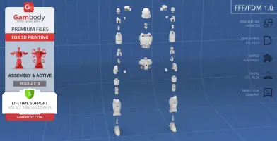
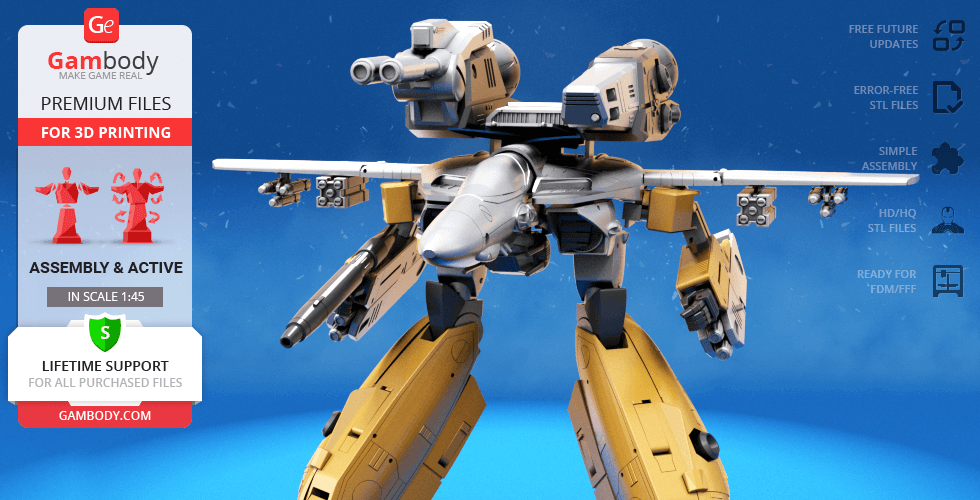
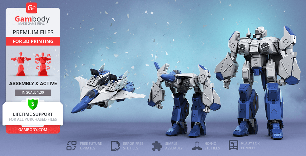
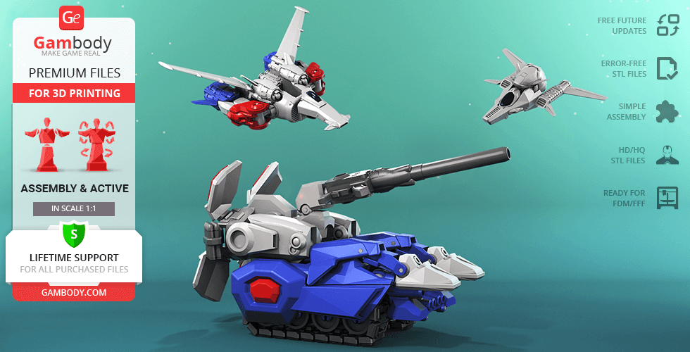
Robotech VR-052 Cyclone 3D Printing Model comes in 1 version for FFF/FDM 3D printers. STL files of the version are available for download after the purchase.
Detailed information about this 3D printing model is available in the DESCRIPTION section.
ABOUT THIS 3D MODEL
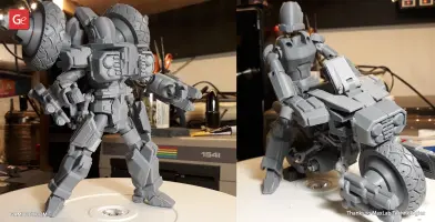
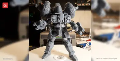
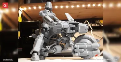
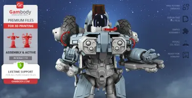
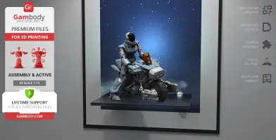
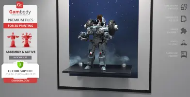
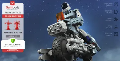
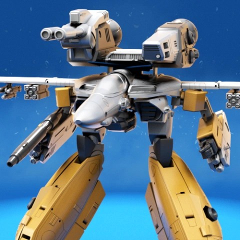
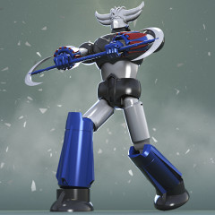
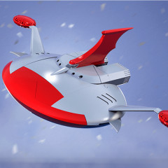
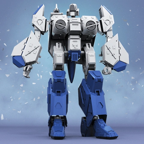
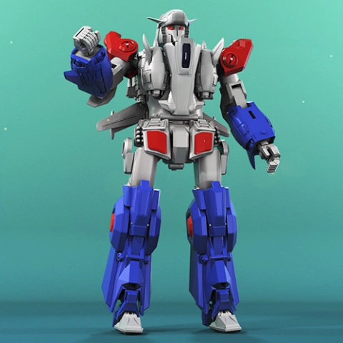
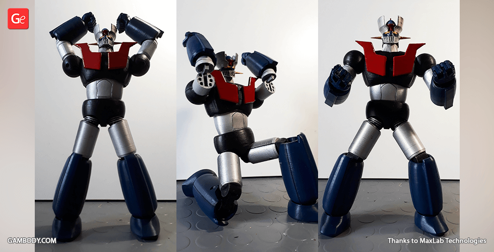
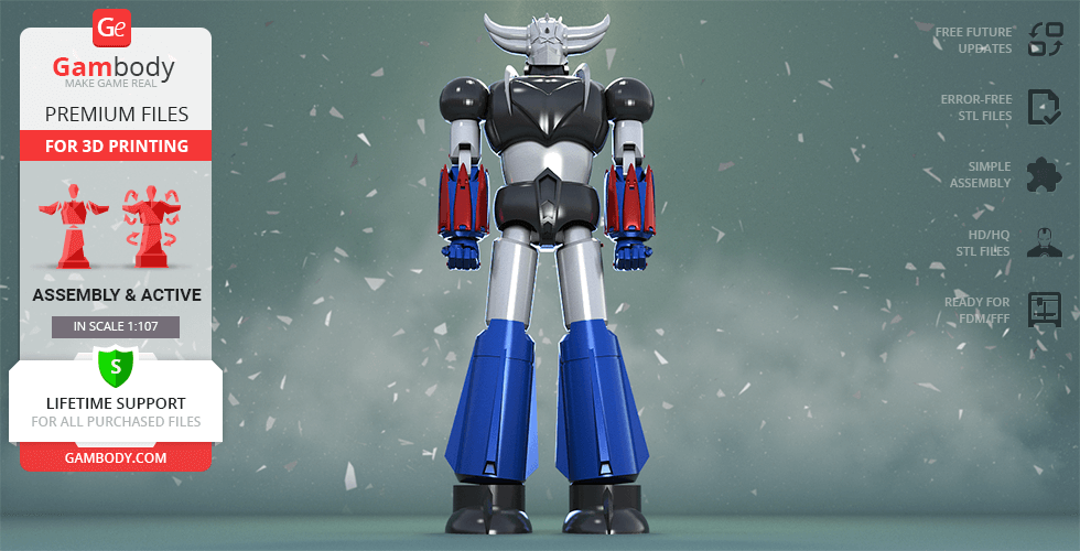
VR-052 Cyclone is a variable mecha unit that comes in two modes - a heavy-duty motorcycle and a formidable Battloid. Composed of various advanced superalloys, this unique creation of robotechnology became one of the stars of Japanese anime series “Genesis Climber MOSPEADA”. Inspired by Japanese sci-fi, the author of the VR-052 model displayed impressive engineering skills by creating a fully transformable Veritech Cyclone robot! The 3D artist mentioned that he did his best to stand by the original design of the mecha, but in order to make the resulting model compatible with 3D printing, the author had to make compromises. Anyway, just one look at the Cyclone for 3D printing is enough to see that this project may become a dream come true of any Robotech enthusiast. VR-052 Cyclone for 3D printing is practically comprised of two separate models. You’ve got a highly poseable pilot that can be placed driving the fully transformable motorcycle. The actual transformation of the cycle into the Armour mode of the mecha requires neither addition nor removal of any assembly parts! Every single piece has its designated place in both modes and once transformed the Armour will only need the pilot to occupy a position inside of it. The whole project took its author circa 190 hours and he even made sure to prepare a video of the actual transformation that you can see by clicking the “Assembly video” button. We say that you shouldn’t hesitate at all - just order the STL files and get yourself a very own Veritech transformer!
ADAPTATION FOR 3D PRINTING
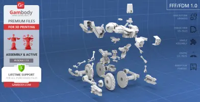
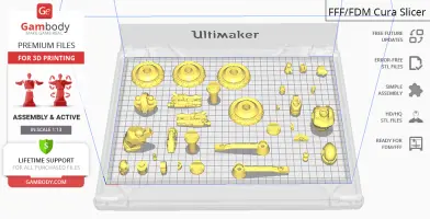
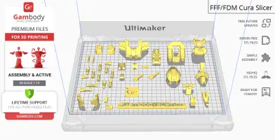
VR-052 Cyclone model for 3D printing is a highly articulated assembly model and its moderation and adaptation for different types of 3D printers took Gambody team 38 hours in total. In order to ensure the robot’s transformation between two modes, Cyclone was divided into many assembly parts. For you to switch the assembled Cyclone between Motorcycle and Armour modes all model’s joints were designed to presuppose the introduction of certain mechanisms. All the assembly parts are provided in STL files in recommended positions that were worked out in order to ensure the smoothness of details’ surfaces after printing and so that the 3D printing beginners won't face difficulties when placing the parts on a build plate. In order to assemble the model, you will need one 5x48 mm self-tapping screw and short pieces of 1.75 PLA to make pins. Apply the glue where you feel appropriate. Make sure to watch "Assembly video" in the photo preview section where you can also see the full transformation from motorcycle mode into armour mode filmed by the author of the model.
The model is saved in STL files, a format supported by most 3D printers. All STL files for 3D printing have been checked in Netfabb and no errors were shown.
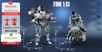
The model's scale was calculated from VR-052 Cyclone's actual height in Armour mode that is 2130 mm. The 3D printing model's chosen scale is 1/13 for the FFF/FDM version.
VERSION SPECIFICATIONS
FFF/FDM 1.0 version features:
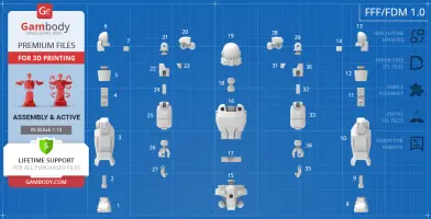
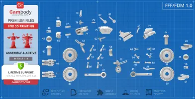
- Contains 82 parts;
- In Motorcycle mode a printed model stands 154 mm tall, 104 mm wide, 187 mm deep;
- In Armour mode - 182 mm tall, 146 mm wide, 115 mm deep;
- Each robot’s joint is articulated which allows the model's transformation;
- The model can be assembled with 1.75 PLA pins and one 5x48 mm screw;
- Watch "Assembly video" to see the screw coloured red and pins - yellow;
- We recommend that you watch the assembly video till the end to see the motorcycle transform into a Battloid mecha;
- All parts are divided in such a way that you will print them with the smallest number of support structures.
WHAT WILL YOU GET AFTER PURCHASE?
- STL files of VR-052 Cyclone Model for 3D printing which consist of 82 parts;
- 1 version of files for this model for FFF/FDM;
- High-poly detailed model of VR-052 Cyclone;
- Detailed settings that we provide as a recommendation for Cura , Simplify3D and Slic3r for the best print;
- Full technical support from the Gambody Support Team.
You can get the model of VR-052 Cyclone for 3D Printing immediately after the purchase! Just click the green Buy button in the top-right corner of the model’s page. You can pay with PayPal or your credit card.
Watch the tutorial on how to assemble VR-052 Cyclone 3D Printing Model at Gambody YouTube channel.
Also, you may like more Robotech 3D Printing Models as well as other Robot 3D Printing Models.
_______
FAQ:
Where can I print a model if I have no printer?
How to get started with 3D printing?
How to set up my 3D printer?
How to choose right 3D model print bed positioning?
How to paint printed figurine?
Generic
This model was tested in Cura 3.4.1 and printed on an Ultimaker 2 in PLA material. Below you can find printing recommendations for Cura, Simplify3D and Slic3r softwares.
Recommendations: Use ABS or PLA Plus filament to print more durable and friction resistant details.
To avoid printing problems, we recommend the following settings:
Quality
Layer Height: 0.1 mm
Initial Layer Height: 0.3 mm
Line Width: 0.4 mm
Wall Line Width: 0.4 mm
Outer Wall Line Width: 0.4 mm
Inner Wall(s) Line Width: 0.4 mm
Top/Bottom Line Width: 0.4 mm
Infill Line Width: 0.4 mm
Skirt/Brim Line Width: 0.4 mm
Support Line Width: 0.4 mm
Initial Layer Line Width: 100%
Shell
Wall Thickness: 0.8 mm
Wall Line Count: 2
Outer Wall Wipe Distance: 0.2 mm
Top Surface Skin Layers: 0
Top/Bottom Thickness: 0.8 mm
Top Thickness: 0.8 mm
Top Layers: 8
Bottom Thickness: 0.8 mm
Bottom Layers: 8
Top/Bottom Pattern: Lines
Bottom Pattern Initial Layer: Lines
Top/Bottom Line Directions: [ ]
Outer Wall Inset: 0 mm
Compensate Wall Overlaps: Check
Compensate Outer Wall Overlaps: Check
Compensate Inner Wall Overlaps: Check
Fill Gaps Between Walls: Everywhere
Filter Out Tiny Gaps: Check
Horizontal Expansion: 0 mm
Initial Layer Horizontal Expansion: 0 mm
Z Seam Alignment: Sharpest Corner
Seam Corner Preference: Hide Seam
Ignore Small Z Gaps: Check
Extra Skin Wall Count: 1
Infill
Infill Density: 80%
Infill Line Distance: 4.0 mm
Infill Pattern: Grid
Infill Line Directions: [ ]
Infill X Offset: 0 mm
Infill Y Offset: 0 mm
Infill Overlap Percentage: 10%
Infill Overlap: 0.04 mm
Skin Overlap Percentage: 5%
Skin Overlap: 0.02 mm
Infill Wipe Distance: 0.1 mm
Infill Layer Thickness: 0.1 mm
Gradual Infill Steps: 1
Gradual Infill Steps Height: 1.5 mm
Infill Before Walls: Check
Minimum Infill Area: 0 mm2
Skin Removal Width: 0.8 mm
Top Skin Removal Width: 0.8 mm
Bottom Skin Removal Width: 0.8 mm
Skin Expand Distance: 0.8
Top Skin Expand Distance: 0.8
Bottom Skin Expand Distance: 0.8
Maximum Skin Angle for Expansion: 90˚
Minimum Skin Width for Expansion: 0.0
Material
Initial Layer Flow: 100%
Enable Retraction: Check
Retraction Extra Prime Amount: 0 mm3
Retraction Minimum Travel: 0.8 mm
Maximum Retraction Count: 90
Minimum Extrusion Distance Window: 6.5 mm
Nozzle Switch Retraction Distance: 16 mm
Nozzle Switch Retraction Speed: 20 mm/s
Nozzle Switch Retract Speed: 20 mm/s
Nozzle Switch Prime Speed: 20 mm/s
Speed
Print Speed: 45 mm/s
Infill Speed: 45 mm/s
Wall Speed: 22.5 mm/s
Outer Wall Speed: 22.5 mm/s
Inner Wall Speed: 45 mm/s
Top/Bottom Speed: 15 mm/s
Travel Speed: 45 mm/s
Initial Layer Speed: 22.5 mm/s
Initial Layer Print Speed: 22.5 mm/s
Initial Layer Travel Speed: 30 mm/s
Skirt/Brim Speed: 30 mm/s
Maximum Z Speed: 0 mm/s
Number of Slower Layers: 2
Travel
Combing Mode: All
Avoid Printed Parts when Traveling: Check
Travel Avoid Distance: 0.625 mm
Layer Start X: 0.0 mm
Layer Start Y: 0.0 mm
Cooling
Enable Print Cooling: Check
Fan Speed: 100%
Regular Fan Speed: 100%
Maximum Fan Speed: 100%
Regular/Maximum Fan Speed Threshold: 10 s
Initial Fan Speed: 0%
Regular Fan Speed at Height: 0.3 mm
Regular Fan Speed at Layer: 2
Minimum Layer Time: 5 s
Minimum Speed: 10 mm/s
Support
Generate Support: Check
Support Placement: Everywhere
Support Overhang Angle: 50°
Support Pattern: Zig Zag
Connect Support ZigZags: Check
Support Density: 15 %
Support Line Distance: 3 mm
Support Z Distance: 0.1 mm
Support Top Distance: 0.1 mm
Support Bottom Distance: 0.1 mm
Support X/Y Distance: 1 mm
Support Distance Priority: Z overrides X/Y
Minimum Support X/Y Distance: 0.25 mm
Support Stair Step Height: 0.3 mm
Support Stair Step Maximum Width: 5.0 mm
Support Join Distance: 2.0 mm
Support Horizontal Expansion: 0.2 mm
Support Infill Layer Thickness: 0.1 mm
Gradual Support Infill Steps: 0
Use Towers: Check
Tower Diameter: 3.0 mm
Minimum Diameter: 3.0 mm
Tower Roof Angle: 65°
Build Plate Adhesion
Build Plate Adhesion Type: Brim (for all parts of locks use "Skirt")
Skirt/Brim Minimum Length: 250 mm
Brim Width: 8.0 mm
Brim Line Count: 18
Brim Only on Outside: Check
Mesh Fixes
Union Overlapping Volumes: Check
Merged Meshes Overlap: 0.15 mm
Special Modes
Print Sequence: All at Once
Surface Mode: Normal
Experimental
Slicing Tolerance: Middle
Maximum Resolution: 0.01 mm
Flow rate compensation max extrusion offset: 0 mm
Flow rate compensation factor: 100%
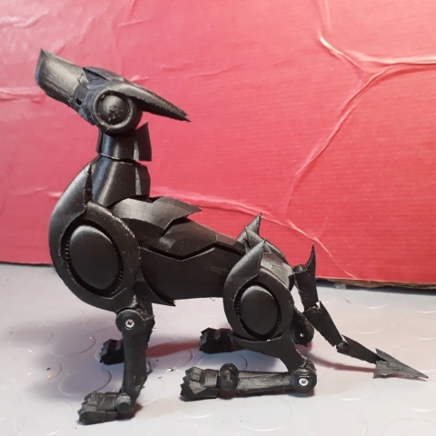
Disclaimer: This model will look outstanding if printed on SLA/SLS 3D printer. The accuracy of the model printed on FFF printer can vary from the result shown in the pictures.
This model was tested with PLA material.
To avoid printing problems, we recommend the following settings:
Extruder
Nozzle Diameter: 0.4 mm
Extrusion Multiplier: 0.97
Extrusion Width: Auto
Retraction Distance: 5.00 mm
Extra Restart Distance: 0.00 mm
Retraction Vertical Lift: 0.08 mm
Retraction Speed: 5400.0 mm/min
Wipe Distance: 5.00 mm
Layer
Primary Layer Height: 0.2 mm
Top Solid Layers: 8
Bottom Solid Layers: 5
Outline/Perimeter Shells: 2
Outline Direction: Inside-Out
First Layer Height: 90%
First Layer Width: 100%
First Layer Speed: 20%
Additions
Use Skirt/Brim: Check
Skirt Layers: 1
Skirt Offset from Part: 6.00 mm
Skirt Outlines: 5
Infill
Internal Fill Pattern: Fast Honeycomb
External Fill Patern: Rectilinear
Interior Fill Percentage: 80%
Outline Overlap: 22%
Infill Extrusion Width: 100%
Minimum Infill Length: 5.00 mm
Combine Infill Every: 1 layers
External Infill Angle Offsets: 45/-45 deg
Support
Generate Support Material: Check
Support Infill Percentage: 15%
Extra Inflation Distance: 1.00 mm
Support Base Layers: 0
Combine Support Every: 1 layers
Dense Support Layers: 0
Dense Infill Percentage: 70%
Support Type: Normal
Support Pillar Resolution: 5.00 mm
Max Overhang Angle: 60 deg
Horizontal Offset From Part: 0.50 mm
Upper Vertical Separation Layers: 1
Lower Vertical Separation Layers: 1
Support Infill Angles: 45 deg
Temperature
Extruder 1 Temperature: 210
Heated Bed: 60
Cooling
Increase fan speed for layers below: 45.0 sec
Maximum Cooling fan speed: 50%
Bridging fan speed override: 100%
Speeds
Default Printing Speed: 4800.0 mm/min
Outline Underspeed: 50%
Solid Infill Underspeed: 80%
Support Structure Underspeed: 80%
X/Y Axis Movement Speed: 10800.0 mm/min
Z Axis Movemen Speed: 1002.0 mm/min
Adjust printing speed for layers below: 15.0 sec
Allow speed reduction down to: 20%
Other
Unsupported area threshold: 20.0 sq m
Layer height
Layer height: 0.1 mm
First layer height: 90%
Vertical shells
Perimeters: 2
Horizontal shells
Soid layers:
Top: 8
Bottom: 5
Quality
Detect thin walls: Check
Detect bridging perimeters: Check
Advanced
Seam position: Random
Infill
Fill density: 80%
Fill pattern: Honeycomb
Top/bottom fill pattern: Rectilinear
Reducing printing time
Combine infill every: 1 layers
Advanced
Solid infill every: 0 layers
Fill angle: 25 deg
Solid infill threshold area: 0mm
Skirt
Loops: 2
Distance from object: 6 mm
Skirt height: 1 layers
Minimum extrusion length: 4 mm
Brim
Brim width: 10 mm
Support material
Generate support material: Check
Overhang threshold: 45 deg
Enforce support for the first: 3 layers
Raft
Raft layers: 0 layers
Options for support material and raft
Contact Z distance: 0.1 mm
Pattern: Rectilinear
Patter spacing: 2 mm
Pattern angle: 0 deg
Interface layers: 2 layers
Interface pattern spacing: 0.2 mm
Speed for print moves
Perimeters: 60 mm/s
Small perimeters: 20 mm/s
External perimeters: 20 mm/s
Infill: 60 mm/s
Solid infill: 60 mm/s
Top solid infill: 30 mm/s
Support material: 50 mm/s
Support material interface: 100%
Bridges: 30 mm/s
Gap fill: 50 mm/s
Speed for non-print moves
Travel: 60 mm/s
Modifiers
First layer speed: 30 mm/s
Acceleration control
Perimeters: 800 mm/s
Infill: 1500 mm/s
Bridge: 1000 mm/s
First layer: 1000 mm/s
Default: 1000 mm/s
Autospeed
Max print speed: 100 mm/s
Max volumetrix speed: 0 mm/s
Extrusion width
Default extrusion width: 0.42 mm
First layer: 0.42 mm
Perimeters: 0.42 mm
External perimeters: 0.42 mm
Infill: 0.42 mm
Solid infill: 0.42 mm
Top solid infill: 0.42 mm
Support material: 0.42 mm
Overlap
Infill/Perimeters overlap: 20%
Flow
Bridge flow ratio: 0.95
Other
XY Size Compensation: 0 mm
Threds: 8
Resolution: 0 mm


Comments