This 3D Model consists of files in StereoLithography (.Stl) format that is optimized for 3D printing.
Before printing the files, we strongly recommend reading the PRINTING DETAILS section.
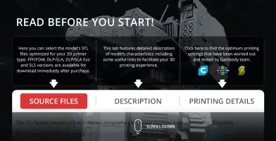
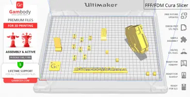
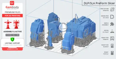
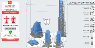
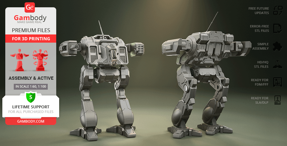
MWO Stalker 3D Printing Model comes in 2 versions for each 3D printer type (FFF/FDM, DLP/SLA/SLS). Files for each version are available for download after the purchase.
Detailed information about this 3D printing model is available in the DESCRIPTION section.
ABOUT THIS 3D MODEL
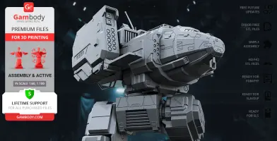
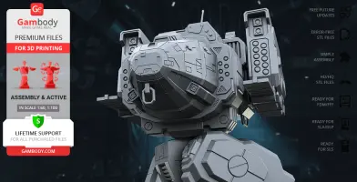
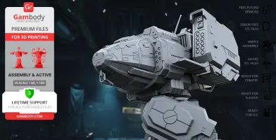
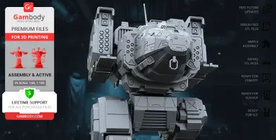
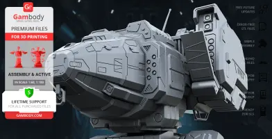
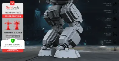
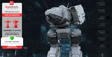
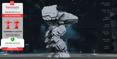
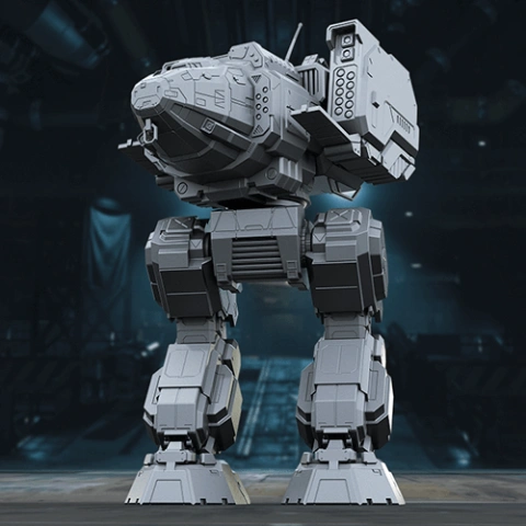
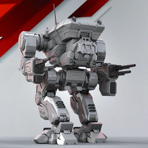
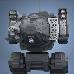
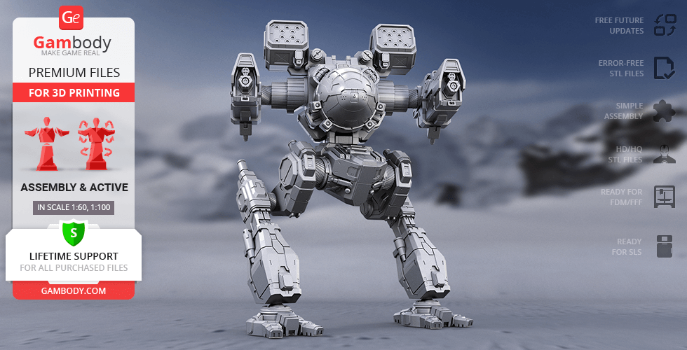
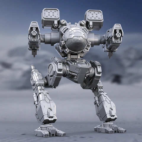
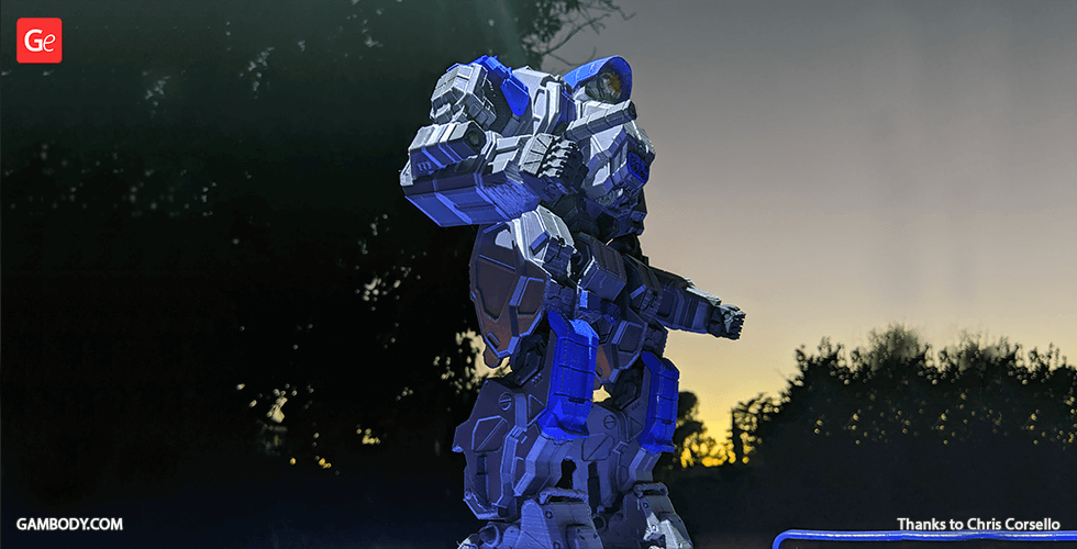
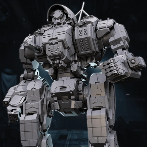
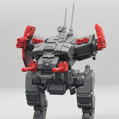
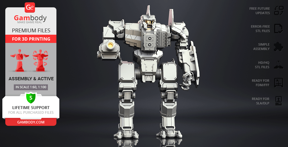
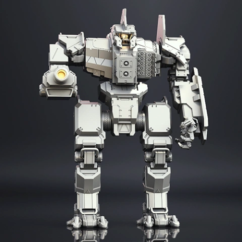
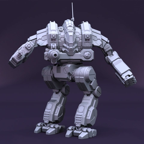
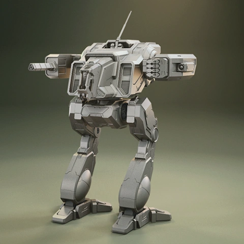
The Stalker is a heavily-armoured BattleMech who is considered by many MWO fans to be one of the best Assault-weight Mechs in its class. An over-gunned 85-ton Stalker is distinguished by rather a bizarre appearance and slow and steady pace that the robot settles for in order to carry the ridiculous amount of weaponry. The assault Mech is rather common in both the Inner Sphere and Periphery and is notorious for its poor heat management. They say, one Alpha Strike is enough to shut the Stalker down and even those twenty heat sinks that are installed wouldn’t deal with the overload. The author of Stalker model for 3D printing spent 118 hours to create the highly requested BattleMech to join both the abundant MWO category on the marketplace and the 3D printed collections of MechWarrior universe fans. As expected, the 3D printing Stalker lacks arms but this shortcoming is compensated by plenty of room in the internal spaces for weapons and armament that make the Mech perfect for urban combat within the video game. Stalker looks and definitely is sturdy - the battle machine is known to be able to handle a great number of enemies’ kicks and stand against the hottest of blows. The Mech is fearsome, powerful and could even be called a classic jack of all trades if it wasn’t for the considerably low speed. The MechWarrior universe offers a wide variety of robots to fulfil any task required on the battlefield which furthermore inspires artists of all kinds to depict them in unique artworks. take advantage of it - get yourself your very own Stalker model now, STL files are ready for order.
ADAPTATION FOR 3D PRINTING
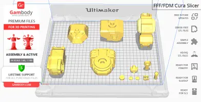
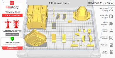
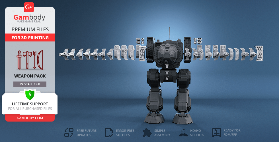
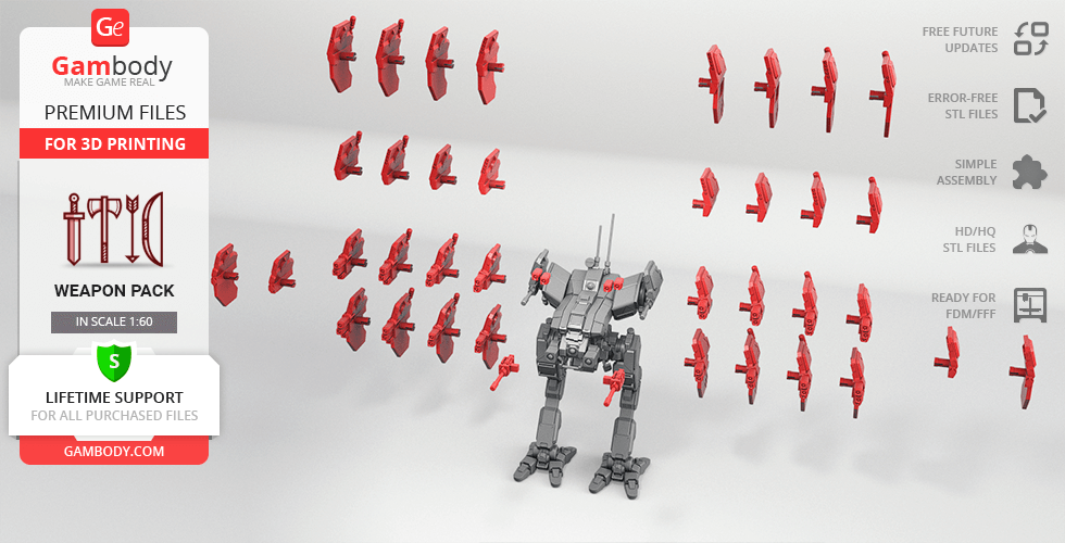
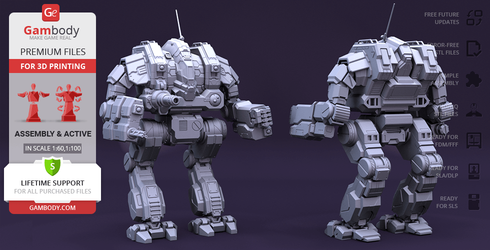
MWO Stalker 3D printing model is an action assembly model and its moderation and adaptation for different types of 3D printers took Gambody team 36 hours in total. The model’s cutting was chosen by our team to minimise the amount of filament needed for generated support. Model is cut in many assembly parts that are provided in STL files in recommended positions that were worked out so to ensure the smoothness of the details’ surfaces after printing and that the 3D printing beginners won't face difficulties when placing the parts on a build plate. To allow the multidirectional movement and rotation of the Stalker model, the ball-and-socket joints and one-axis joints with lockers were introduced. The joints that ensure the Mech's movability are provided as separate files for you to be able to print them again if the joints' friction happens to lose rigidity. The LRM-10 missile launchers, as well as other armaments Stalker is equipped with are assembled in such a way that can be potentially replaced when the alternative Guns Pack for the Mech is released. A separate Weapon Pack is already available for this MWO Stalker 3D printing model.
The model is saved in STL files, a format supported by most 3D printers. All STL files for 3D printing have been checked in Netfabb and no errors were shown.
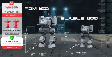
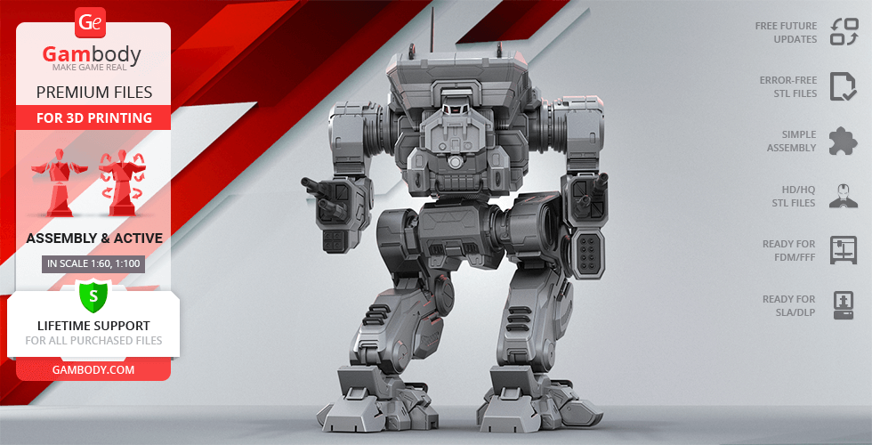
The model's scale was calculated from Stalker's actual height that is 15800 mm. The 3D printing model's chosen scale is 1/60 for the FFF/FDM version and 1/100 for the DLP/SLA/SLS versions.
VERSIONS' SPECIFICATIONS
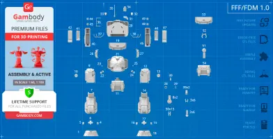
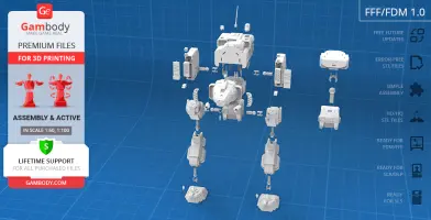
FFF/FDM 1.0 version features:
- Contains 54 parts;
- A printed model is 303 mm tall, 153 mm wide, 185 mm deep;
- Made with several sets of special joints to ensure the model's articulation;
- Assembly kit includes locks to connect the parts without glue. One lock 50_body_lock_X13 needs to be printed 13 times;
- There is a separate Weapon Pack available for this version of MWO Stalker 3D printing model;
- All parts are divided in such a way that you will print them with the smallest number of support structures and so to ensure the smoothness of the details’ surfaces.
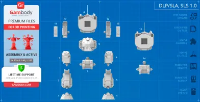
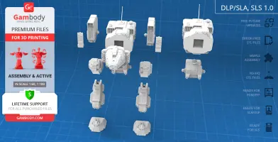
DLP/SLA/SLS 1.0 version features:
- Contains 15 parts;
- A printed model is 182 mm tall, 92 mm wide, 110 mm deep;
- Made with special joints to ensure the model's articulation;
- All parts are divided in such a way to fit the build plates and to ensure that support structures are generated where needed.
WHAT WILL YOU GET AFTER PURCHASE?
- STL files of MWO Stalker 3D Printing Model which consist of 69 parts;
- 2 versions of files of this model for FFF/FDM and DLP/SLA/SLS printers;
- High-poly detailed model of MWO Stalker;
- Detailed settings that we provide as a recommendation for Cura , Simplify3D and Slic3r for the best print;
- Full technical support from the Gambody Support Team.
You can get the model of MWO Stalker for 3D printing immediately after the purchase! Just click the green Buy button in the top-right corner of the model’s page. You can pay with PayPal or your credit card.
Watch the tutorial on how to assemble MWO Stalker 3D Printing Model at Gambody YouTube channel.
Also, you may like other Mech Warrior 3D Printing Models.
_______
FAQ:
Where can I print a model if I have no printer?
How to get started with 3D printing?
How to set up my 3D printer?
How to choose right 3D model print bed positioning?
How to paint printed figurine?
Generic
This model was tested in Cura 3.4.1 and printed on an Ultimaker 2 in PLA material. Below you can find printing recommendations for Cura, Simplify3D and Slic3r softwares.
Recommendations: For all parts of Locks you need to change "Brim" type to "Skirt" in Build Plate Adhesion section.
To avoid printing problems, we recommend the following settings:
Quality
Layer Height: 0.1 mm
Initial Layer Height: 0.3 mm
Line Width: 0.4 mm
Wall Line Width: 0.4 mm
Outer Wall Line Width: 0.4 mm
Inner Wall(s) Line Width: 0.4 mm
Top/Bottom Line Width: 0.4 mm
Infill Line Width: 0.4 mm
Skirt/Brim Line Width: 0.4 mm
Support Line Width: 0.4 mm
Initial Layer Line Width: 100%
Shell
Wall Thickness: 0.8 mm
Wall Line Count: 2
Outer Wall Wipe Distance: 0.2 mm
Top Surface Skin Layers: 0
Top/Bottom Thickness: 0.8 mm
Top Thickness: 0.8 mm
Top Layers: 8
Bottom Thickness: 0.8 mm
Bottom Layers: 8
Top/Bottom Pattern: Lines
Bottom Pattern Initial Layer: Lines
Top/Bottom Line Directions: [ ]
Outer Wall Inset: 0 mm
Compensate Wall Overlaps: Check
Compensate Outer Wall Overlaps: Check
Compensate Inner Wall Overlaps: Check
Fill Gaps Between Walls: Everywhere
Filter Out Tiny Gaps: Check
Horizontal Expansion: 0 mm
Initial Layer Horizontal Expansion: 0 mm
Z Seam Alignment: Sharpest Corner
Seam Corner Preference: Hide Seam
Ignore Small Z Gaps: Check
Extra Skin Wall Count: 1
Infill
Infill Density: 20%
Infill Line Distance: 4.0 mm
Infill Pattern: Grid
Infill Line Directions: [ ]
Infill X Offset: 0 mm
Infill Y Offset: 0 mm
Infill Overlap Percentage: 10%
Infill Overlap: 0.04 mm
Skin Overlap Percentage: 5%
Skin Overlap: 0.02 mm
Infill Wipe Distance: 0.1 mm
Infill Layer Thickness: 0.1 mm
Gradual Infill Steps: 1
Gradual Infill Steps Height: 1.5 mm
Infill Before Walls: Check
Minimum Infill Area: 0 mm2
Skin Removal Width: 0.8 mm
Top Skin Removal Width: 0.8 mm
Bottom Skin Removal Width: 0.8 mm
Skin Expand Distance: 0.8
Top Skin Expand Distance: 0.8
Bottom Skin Expand Distance: 0.8
Maximum Skin Angle for Expansion: 90˚
Minimum Skin Width for Expansion: 0.0
Material
Initial Layer Flow: 100%
Enable Retraction: Check
Retraction Extra Prime Amount: 0 mm3
Retraction Minimum Travel: 0.8 mm
Maximum Retraction Count: 90
Minimum Extrusion Distance Window: 6.5 mm
Nozzle Switch Retraction Distance: 16 mm
Nozzle Switch Retraction Speed: 20 mm/s
Nozzle Switch Retract Speed: 20 mm/s
Nozzle Switch Prime Speed: 20 mm/s
Speed
Print Speed: 45 mm/s
Infill Speed: 45 mm/s
Wall Speed: 22.5 mm/s
Outer Wall Speed: 22.5 mm/s
Inner Wall Speed: 45 mm/s
Top/Bottom Speed: 15 mm/s
Travel Speed: 45 mm/s
Initial Layer Speed: 22.5 mm/s
Initial Layer Print Speed: 22.5 mm/s
Initial Layer Travel Speed: 30 mm/s
Skirt/Brim Speed: 30 mm/s
Maximum Z Speed: 0 mm/s
Number of Slower Layers: 2
Travel
Combing Mode: All
Avoid Printed Parts when Traveling: Check
Travel Avoid Distance: 0.625 mm
Layer Start X: 0.0 mm
Layer Start Y: 0.0 mm
Cooling
Enable Print Cooling: Check
Fan Speed: 100%
Regular Fan Speed: 100%
Maximum Fan Speed: 100%
Regular/Maximum Fan Speed Threshold: 10 s
Initial Fan Speed: 0%
Regular Fan Speed at Height: 0.3 mm
Regular Fan Speed at Layer: 2
Minimum Layer Time: 5 s
Minimum Speed: 10 mm/s
Support
Generate Support: Check
Support Placement: Everywhere
Support Overhang Angle: 50°
Support Pattern: Zig Zag
Connect Support ZigZags: Check
Support Density: 15 %
Support Line Distance: 3 mm
Support Z Distance: 0.1 mm
Support Top Distance: 0.1 mm
Support Bottom Distance: 0.1 mm
Support X/Y Distance: 1 mm
Support Distance Priority: Z overrides X/Y
Minimum Support X/Y Distance: 0.25 mm
Support Stair Step Height: 0.3 mm
Support Stair Step Maximum Width: 5.0 mm
Support Join Distance: 2.0 mm
Support Horizontal Expansion: 0.2 mm
Support Infill Layer Thickness: 0.1 mm
Gradual Support Infill Steps: 0
Use Towers: Check
Tower Diameter: 3.0 mm
Minimum Diameter: 3.0 mm
Tower Roof Angle: 65°
Build Plate Adhesion
Build Plate Adhesion Type: Brim (for all parts of locks use "Skirt")
Skirt/Brim Minimum Length: 250 mm
Brim Width: 8.0 mm
Brim Line Count: 18
Brim Only on Outside: Check
Mesh Fixes
Union Overlapping Volumes: Check
Merged Meshes Overlap: 0.15 mm
Special Modes
Print Sequence: All at Once
Surface Mode: Normal
Experimental
Slicing Tolerance: Middle
Maximum Resolution: 0.01 mm
Flow rate compensation max extrusion offset: 0 mm
Flow rate compensation factor: 100%
Disclaimer: This model will look outstanding if printed on SLA/SLS 3D printer. The accuracy of the model printed on FFF printer can vary from the result shown in the pictures.
This model was tested with PLA material.
To avoid printing problems, we recommend the following settings:
Extruder
Nozzle Diameter: 0.4 mm
Extrusion Multiplier: 0.97
Extrusion Width: Auto
Retraction Distance: 5.00 mm
Extra Restart Distance: 0.00 mm
Retraction Vertical Lift: 0.08 mm
Retraction Speed: 5400.0 mm/min
Wipe Distance: 5.00 mm
Layer
Primary Layer Height: 0.2 mm
Top Solid Layers: 8
Bottom Solid Layers: 5
Outline/Perimeter Shells: 2
Outline Direction: Inside-Out
First Layer Height: 90%
First Layer Width: 100%
First Layer Speed: 20%
Additions
Use Skirt/Brim: Check
Skirt Layers: 1
Skirt Offset from Part: 6.00 mm
Skirt Outlines: 5
Infill
Internal Fill Pattern: Fast Honeycomb
External Fill Patern: Rectilinear
Interior Fill Percentage: 10%
Outline Overlap: 22%
Infill Extrusion Width: 100%
Minimum Infill Length: 5.00 mm
Combine Infill Every: 1 layers
External Infill Angle Offsets: 45/-45 deg
Support
Generate Support Material: Check
Support Infill Percentage: 15%
Extra Inflation Distance: 1.00 mm
Support Base Layers: 0
Combine Support Every: 1 layers
Dense Support Layers: 0
Dense Infill Percentage: 70%
Support Type: Normal
Support Pillar Resolution: 5.00 mm
Max Overhang Angle: 60 deg
Horizontal Offset From Part: 0.50 mm
Upper Vertical Separation Layers: 1
Lower Vertical Separation Layers: 1
Support Infill Angles: 45 deg
Temperature
Extruder 1 Temperature: 210
Heated Bed: 60
Cooling
Increase fan speed for layers below: 45.0 sec
Maximum Cooling fan speed: 50%
Bridging fan speed override: 100%
Speeds
Default Printing Speed: 4800.0 mm/min
Outline Underspeed: 50%
Solid Infill Underspeed: 80%
Support Structure Underspeed: 80%
X/Y Axis Movement Speed: 10800.0 mm/min
Z Axis Movemen Speed: 1002.0 mm/min
Adjust printing speed for layers below: 15.0 sec
Allow speed reduction down to: 20%
Other
Unsupported area threshold: 20.0 sq m
Layer height
Layer height: 0.1 mm
First layer height: 90%
Vertical shells
Perimeters: 2
Horizontal shells
Soid layers:
Top: 8
Bottom: 5
Quality
Detect thin walls: Check
Detect bridging perimeters: Check
Advanced
Seam position: Random
Infill
Fill desity: 20%
Fill pattern: Honeycomb
Top/bottom fill pattern: Rectilinear
Reducing printing time
Combine infill every: 1 layers
Advanced
Solid infill every: 0 layers
Fill angle: 25 deg
Solid infill threshold area: 0mm
Skirt
Loops: 2
Distance from object: 6 mm
Skirt height: 1 layers
Minimum extrusion length: 4 mm
Brim
Brim width: 10 mm
Support material
Generate support material: Check
Overhang threshold: 45 deg
Enforce support for the first: 3 layers
Raft
Raft layers: 0 layers
Options for support material and raft
Contact Z distance: 0.1 mm
Pattern: Rectilinear
Patter spacing: 2 mm
Pattern angle: 0 deg
Interface layers: 2 layers
Interface pattern spacing: 0.2 mm
Speed for print moves
Perimeters: 60 mm/s
Small perimeters: 20 mm/s
External perimeters: 20 mm/s
Infill: 60 mm/s
Solid infill: 60 mm/s
Top solid infill: 30 mm/s
Support material: 50 mm/s
Support material interface: 100%
Bridges: 30 mm/s
Gap fill: 50 mm/s
Speed for non-print moves
Travel: 60 mm/s
Modifiers
First layer speed: 30 mm/s
Acceleration control
Perimeters: 800 mm/s
Infill: 1500 mm/s
Bridge: 1000 mm/s
First layer: 1000 mm/s
Default: 1000 mm/s
Autospeed
Max print speed: 100 mm/s
Max volumetrix speed: 0 mm/s
Extrusion width
Default extrusion width: 0.42 mm
First layer: 0.42 mm
Perimeters: 0.42 mm
External perimeters: 0.42 mm
Infill: 0.42 mm
Solid infill: 0.42 mm
Top solid infill: 0.42 mm
Support material: 0.42 mm
Overlap
Infill/Perimeters overlap: 20%
Flow
Bridge flow ratio: 0.95
Other
XY Size Compensation: 0 mm
Threds: 8
Resolution: 0 mm


Comments