This 3D Figurine consists of files in StereoLithography (.Stl) format that have been optimized for 3D printing.
Before printing the files, we strongly recommend reading the PRINTING DETAILS section.
Terminator T-1000 Damaged 3D Printing Figurine comes in 4 versions for each 3D printer type (FFF/FDM, DLP/SLA, DLP/SLA Eco and SLS). Files for each version are available for download after the purchase.
Detailed information about this model is available in the DESCRIPTION section.
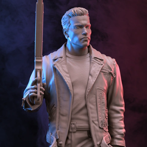
It’s been 10 years since the Terminator from the future tried to kill Sarah Connor. She has now a son, John Connor, who is to lead the Resistance forces to defeat the robots from the future. A group of engineers in Cyberdyne Systems is already working on a revolutionary processor using the remains of the T-800 Terminator on the basis of which SkyNET will be created. At the same time, T-1000 appears in Los Angeles, taking the form of a policeman who was killed immediately after the robot’s arrival. In order to stop him, John Connor sends a reprogrammed T-800 to protect himself in the past. T-800 has barely managed to find the younger John from the past when T-1000 arrives and a shoot-out begins. Being sent to assassinate John, T-1000 leads a continuous pursuit of the protagonists and any means to defeat them is yet to be found. Eventually, in order to kill the T-1000, T-800 throws him in a vat of molten steel together with all evidence of Cyberdyne’s research and destroys himself to hide all traces of future technologies.
ABOUT THIS 3D FIGURINE
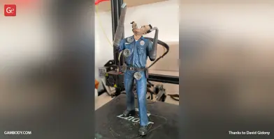
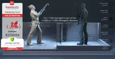
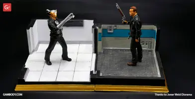
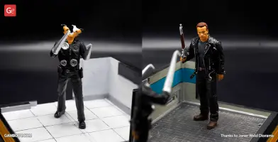
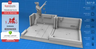
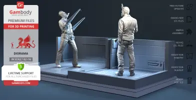
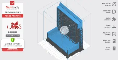
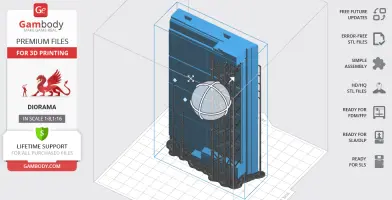
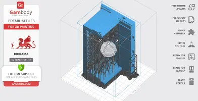
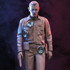
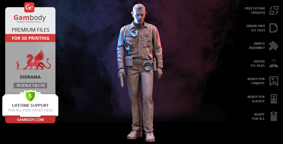
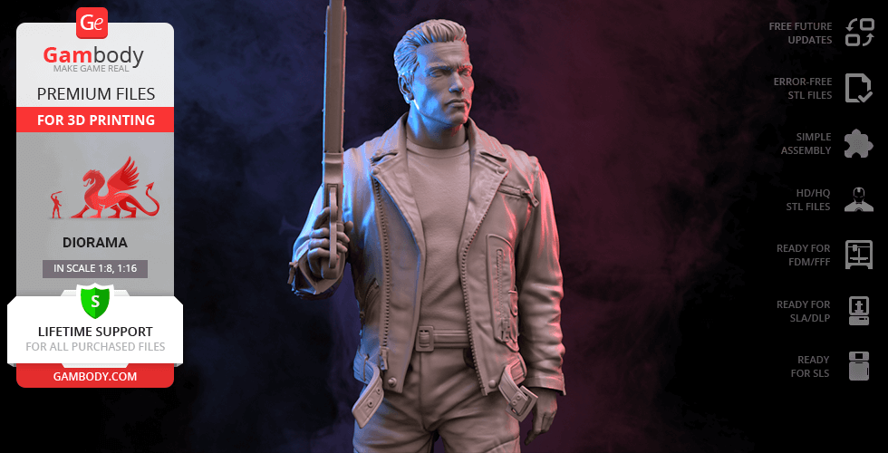
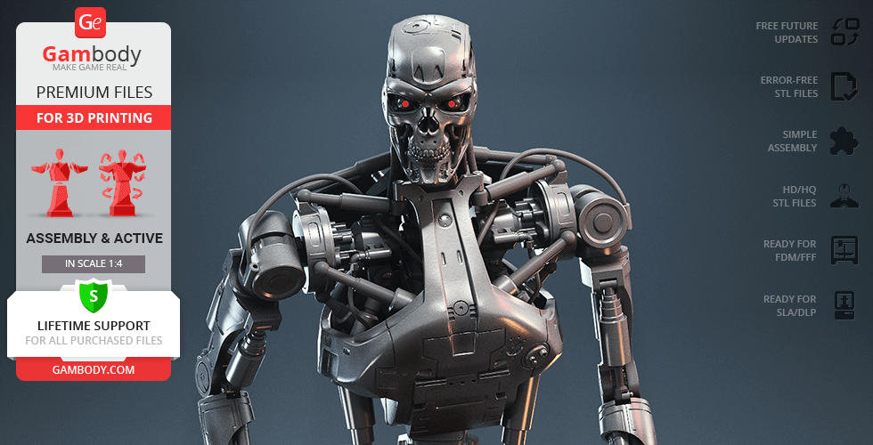
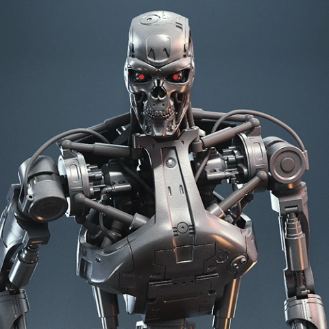
This figure is the second alternative part of diorama "T-800 vs T-1000". The model is saved in STL files, a format supported by most 3D printers.
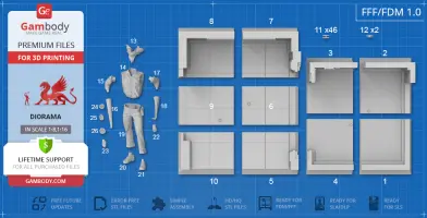
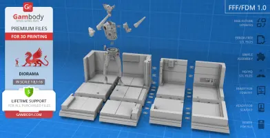
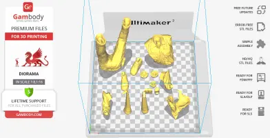
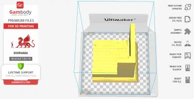
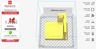
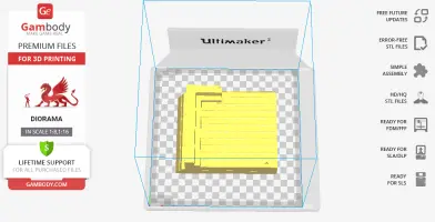
FDM version features: - Contain 26 parts; - Assembly kit includes locks. One part of Lock (11_Ge_lock_10H_(x46)) needs to be printed 46 times; One part of Lock (12_Ge_lock_7S_(x2)) needs to be printed twice; - Made with with bullet marks that can be removed; - Made with a special platform styled as a movie scene; - All parts are divided in such a way that you will print them with the smallest number of support structures.
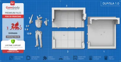
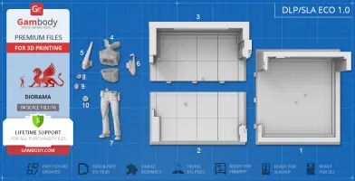
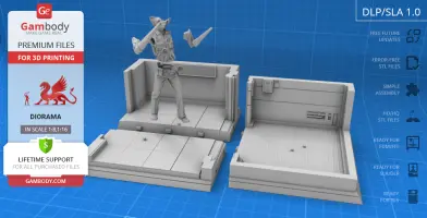
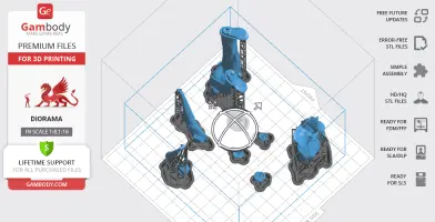
DLP/SLA version features: - Same as FDM but smaller, also made as 10 parts;
DLP/SLA Eco version features: - Same as the DLP/SLA version, but contains parts hollowed out to save resin;
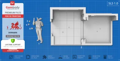
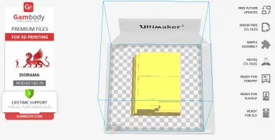
SLS version features: - Same as SLA but made as 5 parts to save your material;
All STL files for 3D printing have been checked in Netfabb and no errors were shown.
Note: Before starting 3D printing the model, read the Printing Details for Cura, Simplify3D or Slic3r Software.
There are 26 parts for FFF/FDM version,10 parts for DLP/SLA, 10 parts for DLP/SLA Eco versions, 5 parts for SLS.
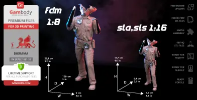
Scale: Terminator T-1000 actual height is 1900 mm. The model’s chosen scale is 1/8 for the FDM version and 1/16 for the DLP/SLA/SLS version.
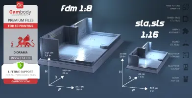
FFF/FDM version dimensions: A printed model is 234 mm tall, 90 mm wide, 128 mm deep - Terminator 147 mm tall, 351 mm wide, 559 mm deep - Platform
DLP/SLA/SLS version dimensions: A printed model is 117 mm tall, 45 mm wide, 64 mm deep - Terminator 74 mm tall, 178 mm wide, 280 mm deep - Platform - Has few details, to keep printing costs down.
WHAT WILL YOU GET AFTER PURCHASE?
- STL files of Terminator T-1000 Damaged 3D Figurine in Diorama for 3D printing which consist of 51 parts; - 4 versions of files for this model for FFF/FDM,DLP/SLA, DLP/SLA Eco and SLS; - High-poly detailed figurine of Terminator T-1000 Damaged; - Detailed settings that we provide for Cura ,Simplify3D and Slic3r for the best print; - Full technical support from the Gambody Support Team.
You can get Model of Terminator T-1000 Damaged for 3D Printing right now! Just click the green Buy button in the top-right corner of the model’s page. You can pay with PayPal or your credit card.
These are basic settings that were tested in Cura 4.8.0 slicer.
The test models were printed on Ultimaker 2, Creality Ender 3, Creality CR-10S Pro V2, Anycubic I3 Mega, Anycubic I3 MegaS 3D printers with PLA and PETG filaments.
Disclaimer: The following printing settings are a recommendation, not an obligation. The parameters can vary depending on the peculiarities of your 3D printer, the material you use and especially the particular assembly part at hand. Each part that any model comprises often needs preliminary review and you are free to tweak the settings the way you find suitable.
Note: - You can scale up the model (downscaling is not recommended!); - All connectors should be printed at 100% Infill; - For all parts of locks (“ge_lock” in “Source files”) you need to change "Brim" type to "Skirt" in Build Plate Adhesionsection.
Quality Layer Height: 0.12 mm (you can also set Layer Height at 0.16 or 0.2mm for 0.4mm nozzles) Initial Layer Height: 0.2 mm (carefully level the print bed and keep your Initial Layer Height the same as the main Layer Height)
Line Width: 0.4 mm Wall Line Width: 0.4 mm Outer Wall Line Width: 0.4 mm Inner Wall(s) Line Width: 0.4 mm Top/Bottom Line Width: 0.4 mm Infill Line Width: 0.4 mm Skirt/Brim Line Width: 0.4 mm Support Line Width: 0.4 mm
Initial Layer Line Width: 100%
Shell Wall Thickness: 0.8 mm Wall Line Count: 2
Outer Wall Wipe Distance: 0.3 mm Top Surface Skin Layers: 0
Top/Bottom Thickness: 0.6 mm Top Thickness: 0.6 mm Top Layers: 5 Bottom Thickness: 0.6 mm Bottom Layers: 5 Initial Bottom Layers: 5
Minimum Wall Flow: 0% Fill Gaps Between Walls: Everywhere Filter Out Tiny Gaps: Check Horizontal Expansion: 0 mm Initial Layer Horizontal Expansion: 0 mm Hole horizontal expansion: 0
Z Seam Alignment: User Specified Z Seam Position: Back Z Seam X: Average length of your printer’s plate (e.g.”150” if your plate is 300mmon the X-axis) Z Seam Y: A value higher than the length of your plate on the Y-axis (e.g. 700)
Seam Corner Preference: Hide Seam Extra Skin Wall Count: 1 Skin Overlap Percentage: 10% Skin Overlap 0.04 mm
Infill Infill Density: 20% (for all smaller parts and for all parts of connectors use 100% Infill) Infill Pattern: Triangles Connect Infill Lines: Check Infill Line Directions: [ ] Infill X Offset: 0 mm Infill Y Offset: 0 mm Infill Line Multiplier: 1 Extra Infill Wall Count: 0
Infill Overlap Percentage: 10-20% Infill Overlap: 0.04 mm
Skin Overlap Percentage: 5% Skin Overlap: 0.02 mm
Infill Wipe Distance: 0 mm Infill Layer Thickness: 0.24 mm Gradual Infill Steps: 0 Infill Before Walls: Check Minimum Infill Area: 0 mm2
Skin Removal Width: 0.8 mm Top Skin Removal Width: 0.8 mm Bottom Skin Removal Width: 0.8 mm
Maximum Skin Angle for Expansion: 90˚ Minimum Skin Width for Expansion: 0.0 Skin Edge Support Thickness: 0 Skin Edge Support Layers: 0
Material Initial Layer Flow: 100% Printing Temperature: See your filament settings Initial Printing Temperature: Your filament settings Final Printing Temperature: Your filament settings Build Plate Temperature: Your filament settings Build Plate Temperature Initial Layer: Your filament settings + 5° Flow: 100% (Important! If you face difficulty printing the model, you may need to adjust the Flow parameter. You may research the topic using the Internet or seek assistance at our Customer Support Team at support@gambody.com)
Speed
You can increase the printing Speed by 20% when you print simple objects. For small/thin parts you need to decrease the Speed by 25% - 50%.
Skirt/Brim Speed: 20 mm/s Z Hop Speed: 5 mm/s Number of Slower Layers: 2 Enable Acceleration Control: Check
When printing simple objects, you need to set all Acceleration parameters at 500 mm/s. For small/thin parts you need to decrease the Acceleration by 50% - 70%.
Travel Enable Retraction: Check Retraction Distance: 4-8 mm, 1-3 mm for Direct Extruder (This is the most important retraction parameter. You can find your optimal value of Retraction Distance by printing any test object, e.g. bridges, towers etc.)
Retraction Extra Prime Amount: 0 mm3 Retraction Minimum Travel: 1.5 mm Maximum Retraction Count: 100 Minimum Extrusion Distance Window: 6,5 - 10 mm Limit Support Retractions: Check Combing Mode: All Max Comb Distance With No Retract: 30 mm Retract Before Outer Wall: Check Avoid Printed Parts When Travelling: Check Avoid Supports When Travelling: Check Travel Avoid Distance: 1 mm Layer Start X: 0.0 mm Layer Start Y: 0.0 mm Z Hop When Retracted: Check Z Hop Height: 0,3 mm
Cooling Enable Print Cooling: Check Fan Speed: 100% Regular Fan Speed: 100% Maximum Fan Speed: 100%
Regular/Maximum Fan Speed Threshold: 10 s Initial Fan Speed: 0% Regular Fan Speed at Height: 0.36 mm Regular Fan Speed at Layer: 3
Minimum Layer Time: 10 s Minimum Speed: 10 mm/s
Support Generate Support: Check Support Structure: Normal (you can try using Tree Support Structure if you have difficulty printing any particular assembly part) Support Placement: Everywhere Support Overhang Angle: 60° (this parameter can range from 30° to 70° depending on the part at hand) Support Pattern: Zig Zag Support Wall Line Count: 1 (stronger support that might be more difficult to remove) 0 (less strong support but is easier to remove)
Support Density: 15% Support Line Distance: 2.6667 mm Initial layer support line distance: 2.667 mm
Support Z Distance: 0.12 mm Support Top Distance: 0.12 mm Support Bottom Distance: 0.12 mm
Support X/Y Distance: 0.8-1 mm Support Distance Priority: Z overrides X/Y Support Stair Step Height: 0.3 mm Support Stair Step Maximum Width: 5.0 mm Support Stair Step Minimum Slope Angle: 10° Support Join Distance: 2.0 mm Support Horizontal Expansion: 0.2 mm Support Infill Layer Thickness: 0.2 mm Gradual Support Infill Steps: 0 Minimum Support Area: 2 mm
Enable Support Interface: Check (generates additional “pillow” on the support structure that leads to a more even surface, but can be difficult to remove in hard-to-reach areas) Enable Support Roof: Check Enable Support Floor: Check
Support Interface Thickness: 0.8 mm Support Roof Thickness: 0.8 mm Support Floor Thickness: 0.8 mm
Support Interface Resolution 0.2 mm Support Interface Density: 50-100% Support Roof Density: 50-100% Support Roof Line Distance: 0.8 mm Support Floor Density: 50-100% Support Floor line Distance: 0.4mm
Support Interface Pattern: Grid Support Roof Pattern: Grid (this parameter should differ from Bottom Pattern Initial Layer in “Shell” section) Support Floor Pattern: Grid
Minimum Support Interface Area: 10mm Minimum Support Roof Area: 10 mm Minimum Support Floor Area: 10 mm
Support Interface Horizontal Expansion: 0.0 mm Support Roof Horizontal Expansion: 0.0 mm Support Floor Horizontal Expansion: 0.0 mm
Fan Speed Override: Check Supported Skin Fan Speed: 100% Use Towers: Check Tower Diameter: 4 mm Minimum Diameter: 3.0 mm Tower Roof Angle: 65°
Build Plate Adhesion Build Plate Adhesion Type: Skirt/Brim (For unsteady parts, and those parts that may come unstuck use “Brim”. For bigger assembly parts that have large adhesion area and for all parts of locks and claws that you want to come out clean use "Skirt") Skirt/Brim Minimum Length: 250 mm Brim Width: 8.0 mm Brim Line Count: 10 Brim Only on Outside: Check
Mesh Fixes Union Overlapping Volumes: Check Merged Meshes Overlap: 0.15 mm
Special Modes Print Sequence: All at Once Surface Mode: Normal
Experimental Slicing Tolerance: Middle Maximum Resolution: 0.01 mm Flow rate compensation max extrusion offset: 0 mm Flow rate compensation factor: 100%
To avoid printing problems, we recommend the following settings:
Extruder Nozzle Diameter: 0.4 mm Extrusion Multiplier: 0.97 Extrusion Width: Auto
Retraction Distance: 5.00 mm Extra Restart Distance: 0.00 mm Retraction Vertical Lift: 0.08 mm Retraction Speed: 5400.0 mm/min
Wipe Distance: 5.00 mm
Layer Primary Layer Height: 0.2 mm Top Solid Layers: 8 Bottom Solid Layers: 5 Outline/Perimeter Shells: 2 Outline Direction: Inside-Out
First Layer Height: 90% First Layer Width: 100% First Layer Speed: 20%
Additions Use Skirt/Brim: Check Skirt Layers: 1 Skirt Offset from Part: 6.00 mm Skirt Outlines: 5
Infill Internal Fill Pattern: Fast Honeycomb External Fill Patern: Rectilinear Interior Fill Percentage: 10% Outline Overlap: 22% Infill Extrusion Width: 100% Minimum Infill Length: 5.00 mm Combine Infill Every: 1 layers
External Infill Angle Offsets: 45/-45 deg
Support Generate Support Material: Check Support Infill Percentage: 15% Extra Inflation Distance: 1.00 mm Support Base Layers: 0 Combine Support Every: 1 layers
Dense Support Layers: 0 Dense Infill Percentage: 70%
Support Type: Normal Support Pillar Resolution: 5.00 mm Max Overhang Angle: 60 deg
Horizontal Offset From Part: 0.50 mm Upper Vertical Separation Layers: 1 Lower Vertical Separation Layers: 1
Support Infill Angles: 45 deg
Temperature Extruder 1 Temperature: 210 Heated Bed: 60
Cooling Increase fan speed for layers below: 45.0 sec Maximum Cooling fan speed: 50% Bridging fan speed override: 100%
Speeds Default Printing Speed: 4800.0 mm/min Outline Underspeed: 50% Solid Infill Underspeed: 80% Support Structure Underspeed: 80% X/Y Axis Movement Speed: 10800.0 mm/min Z Axis Movemen Speed: 1002.0 mm/min
Adjust printing speed for layers below: 15.0 sec Allow speed reduction down to: 20%
You are about to report Terminator T-1000 Damaged for Diorama 3D Printing Figurine | Assembly for violating our
Terms and Conditions.
Please take a few moments to fill in the following information.
Welcome!
We're glad you're here! Before you continue, let's set a few preferences to improve your experience on our marketplace. By clicking "Sure, go ahead", you agree to our use of cookies to make your visit more enjoyable and personalized. This helps us offer you tailored product recommendations and relevant marketing content. Enjoy your time with Gambody, and thank you for choosing us!


Comments