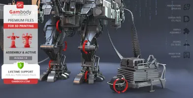
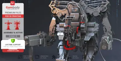
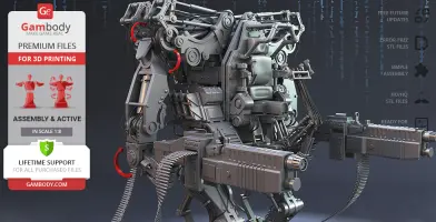
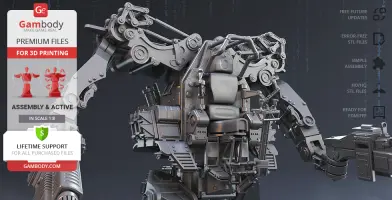
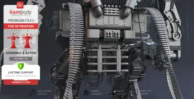
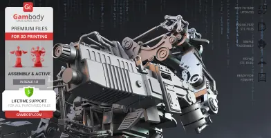
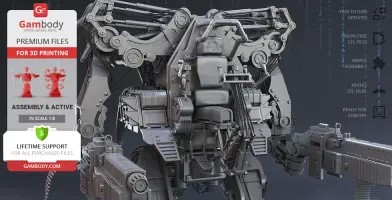
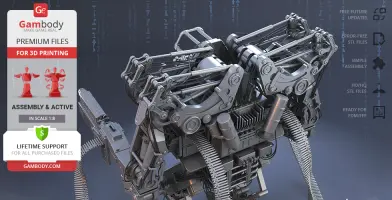
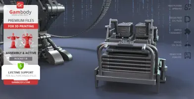
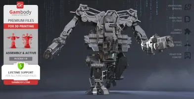
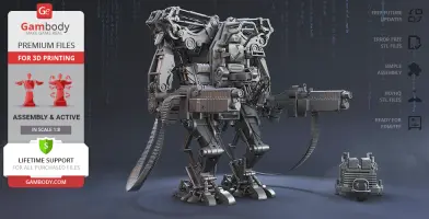
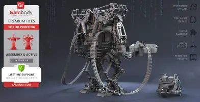
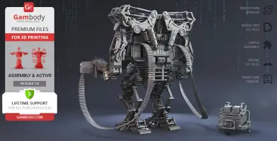
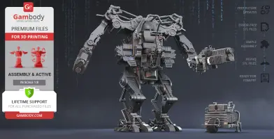
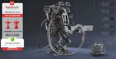
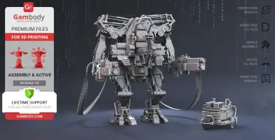
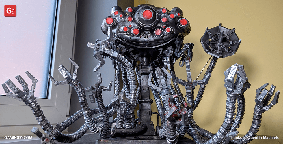
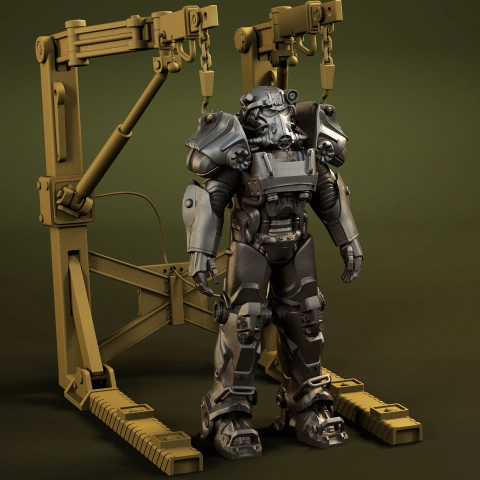
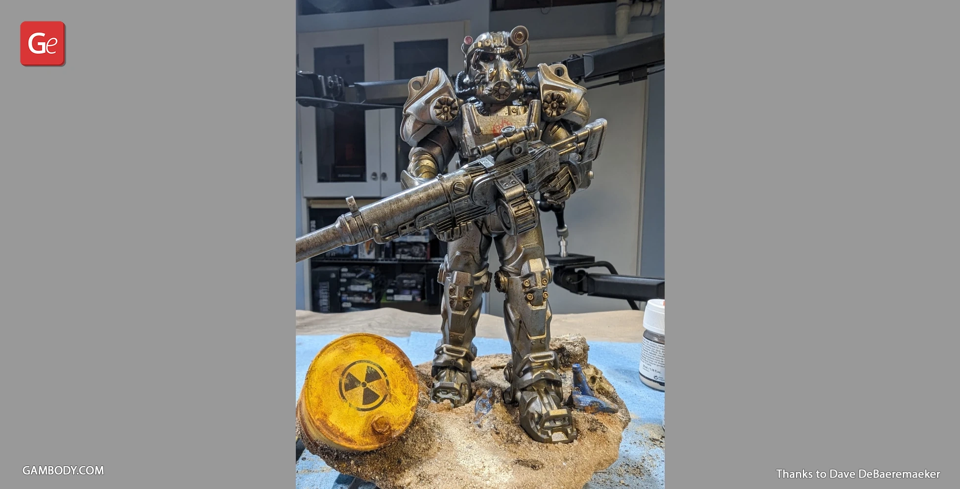
The Armoured Personnel Unit briefly referred to as the APU, is a machinery-equipped piece of a combat force in Zion - the fictional city from The Matrix trilogy. Making the core of the first-line defense force, the walker-shaped hydraulic battle element was piloted by a specially trained operator. Appearing for the first time as early as in the second part of the canonic film, the unit exposes all its glory and dignity in the third installment - The Matrix Revolutions - when strikingly performing its essence mission, i.e. defending the last human city of Zion against the evil swarm of Sentinels. The 3D artist behind the impressive power battle suit mentioned dedicating no less than 190 hours in total for the APU for 3D printing to be as highly-detailed as possible. The signature feature of the unit that is the two huge 30mm rapid-fire cannons are attached to the arms of the 3D printing APU and already have two long ammunition belts inserted ready for action. In order to meet the strict requirements of the biggest Matrix enthusiasts, the 3D artist carefully depicted the finest elements of the mechanized suit. Thus, the 3D printing unit’s pistons, ammo belt feeders, operator’s joysticks, control panel, pilot’s pedal’s, etc. are executed with the painstaking attention to the smallest details. The author of the model also made sure to include the Ammo Loader into the 3D printing kit that even features two additional boxes of ammunition cases! The Matrix Revolutions might have received mixed reviews both from critics and keen movie-goers but one cannot but admit that the Battle for Zion scenes starring the brave Captain Mifune are truly iconic. We urge you not to think twice but embark on the 3D printing Matrix APU project - the STL files are ready for download!
ADAPTATION FOR 3D PRINTING
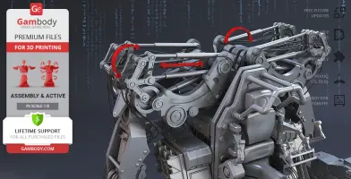
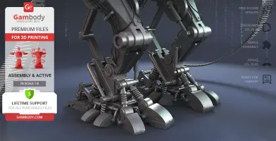
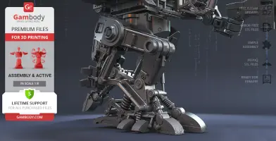
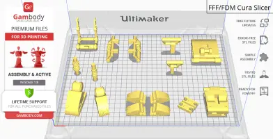
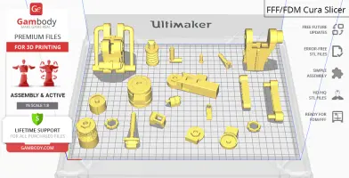
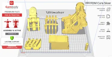
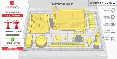
Matrix APU model for 3D printing is a highly articulated action assembly model and its moderation and adaptation for different types of 3D printers took Gambody team 70 hours in total. In order to ensure multidirectional movement of the power battle suit, it was divided into many assembly parts and special mechanisms were introduced into all model’s joints to give you an opportunity to display the APU in a variety of positions, i.e. its pelvis, hips, knees, shins, feet, toes, shoulders, arm cannons, operator's panel, etc. are movable. The pistons all over the APU's body are articulated as well, thus, they move up, down, and retract whenever you bend the model's hips, knees, feet, toes, and shoulders. The cage where the APU’s pilot is meant to operate the machine is equipped with movable console, joystick panel, pedals, and firing levers for the unit to be displayed in your preferred mode. For you to introduce hydraulic cables that connect the APU's parts we recommend that you use either 1.75mm or 2.85mm PLA filament and insert its pieces into designated holes that are designed to fit securely either diameter. The assembly of some of APU's parts (like shoulder flaps) requires additional “pins”. These pins do not come in STL files but can be made out of short pieces of regular 1.75 PLA. All assembly parts are provided in STL files in recommended positions that were worked out so to ensure the smoothness of the details’ surfaces after printing and so that the 3D printing beginners won't face difficulties when placing the parts on a build plate. The joints that ensure the robot’s movability are provided as separate files as well for you to be able to print them again if the joints' friction happens to lose rigidity. We highly recommend that you watch "Assembly video" in the photo preview section before assembling the APU. When downloading any model's file you will also receive "Assembly Manual" for FFF/FDM 1.0 version in PDF format.
The model is saved in STL files, a format supported by most 3D printers. All STL files for 3D printing have been checked in Netfabb and no errors were shown.
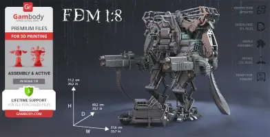
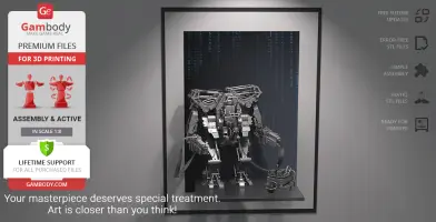
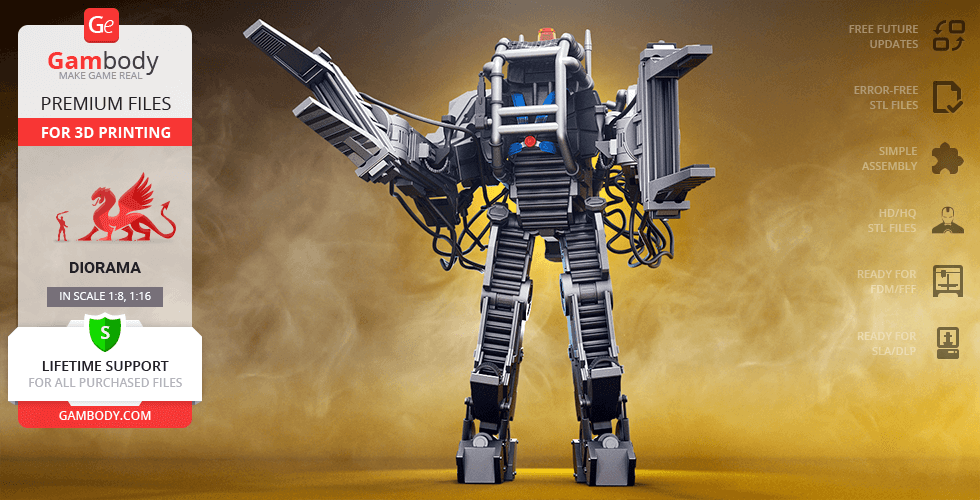
The model's scale was calculated from the actual height of the Armored Personnel Unit that is 4000 mm. The 3D printing model's chosen scale is 1/8 for the FFF/FDM version.
VERSION SPECIFICATIONS
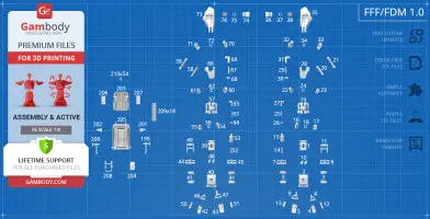
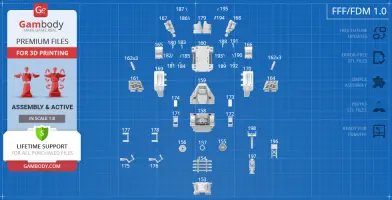
FFF/FDM 1.0 version features:
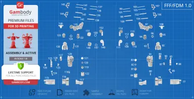
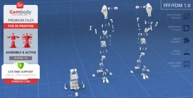
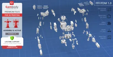
Contains 210 parts;
A printed model is 512 mm tall, 576 mm wide, 602 mm deep;
Made with several sets of special joints to ensure the model's articulation (pelvis, hips, knees, shins, feet, toes, shoulders, armcannons, operator'spanel etc. are movable);
For the highly articulated APU to stand firmly in any position you may choose there was a ratchet mechanism introduced in the model’s main joints and a double-ratchet in the shoulder;
The pistons all over the APU's body are retractable, i.e. they move when you bend the model's articulated hips, knees, feet, toes, shoulders;
Pilot's operating console, joystickpanel, pedals, firinglevers, etc. are fully poseable as well;
The assembly of some of APU's parts (like shoulderflaps) requires additional “pins”. These pins do not come in STL files but can be made out of short pieces of regular 1.75 PLA;
Hydraulic cables that connect the APU's parts are not provided with STL files. You use either 1.75mm or 2.85mm PLA filament of your choice and insert its pieces into designated holes that are designed to fit securely either diameter;
Belt feed is flexible so you can shape it and articulate the assembled APU as you prefer;
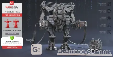
APU comes with the Ammo Loader with two additional boxes of ammocases and a spinningwheel;
Assembly kit includes lock 210_Ge_lock_x54 to attach the model's parts securely without glue that needs to be printed 54 times;
It is highly recommended that you watch "Assembly video" in the photo preview section and read "Assembly Manual" in PDF before assembling the APU;
All parts are divided in such a way that you will print them with the smallest number of support structures.
WHAT WILL YOU GET AFTER PURCHASE?
STL files of Matrix APU for 3D printing which consist of 210 parts;
1 version of files for this model for FFF/FDM;
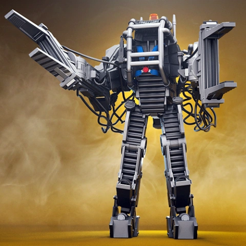
High-poly detailed model of Matrix APU;
AssemblyManual for FFF/FDM 1.0 version in PDF format;
Detailed settings that we provide as a recommendation for Cura , Simplify3D and Slic3r for the best print;- Full technical support from the Gambody Support Team.
You can get the model of Matrix APU for 3D Printing immediately after the purchase! Just click the green Buy button in the top-right corner of the model’s page. You can pay with PayPal or your credit card.
These are basic settings that were tested in Cura 4.8.0 slicer.
The test models were printed on Ultimaker 2, Creality Ender 3, Creality CR-10S Pro V2, Anycubic I3 Mega, Anycubic I3 MegaS 3D printers with PLA and PETG filaments.
Disclaimer: The following printing settings are a recommendation, not an obligation. The parameters can vary depending on the peculiarities of your 3D printer, the material you use and especially the particular assembly part at hand. Each part that any model comprises often needs preliminary review and you are free to tweak the settings the way you find suitable.
Note: - You can scale up the model (downscaling is not recommended!); - All connectors should be printed at 100% Infill; - For all parts of locks (“ge_lock” in “Source files”) you need to change "Brim" type to "Skirt" in Build Plate Adhesionsection.
Quality Layer Height: 0.12 mm (you can also set Layer Height at 0.16 or 0.2mm for 0.4mm nozzles) Initial Layer Height: 0.2 mm (carefully level the print bed and keep your Initial Layer Height the same as the main Layer Height)
Line Width: 0.4 mm Wall Line Width: 0.4 mm Outer Wall Line Width: 0.4 mm Inner Wall(s) Line Width: 0.4 mm Top/Bottom Line Width: 0.4 mm Infill Line Width: 0.4 mm Skirt/Brim Line Width: 0.4 mm Support Line Width: 0.4 mm
Initial Layer Line Width: 100%
Shell Wall Thickness: 0.8 mm Wall Line Count: 2
Outer Wall Wipe Distance: 0.3 mm Top Surface Skin Layers: 0
Top/Bottom Thickness: 0.6 mm Top Thickness: 0.6 mm Top Layers: 5 Bottom Thickness: 0.6 mm Bottom Layers: 5 Initial Bottom Layers: 5
Minimum Wall Flow: 0% Fill Gaps Between Walls: Everywhere Filter Out Tiny Gaps: Check Horizontal Expansion: 0 mm Initial Layer Horizontal Expansion: 0 mm Hole horizontal expansion: 0
Z Seam Alignment: User Specified Z Seam Position: Back Z Seam X: Average length of your printer’s plate (e.g.”150” if your plate is 300mmon the X-axis) Z Seam Y: A value higher than the length of your plate on the Y-axis (e.g. 700)
Seam Corner Preference: Hide Seam Extra Skin Wall Count: 1 Skin Overlap Percentage: 10% Skin Overlap 0.04 mm
Infill Infill Density: 20% (for all smaller parts and for all parts of connectors use 100% Infill) Infill Pattern: Triangles Connect Infill Lines: Check Infill Line Directions: [ ] Infill X Offset: 0 mm Infill Y Offset: 0 mm Infill Line Multiplier: 1 Extra Infill Wall Count: 0
Infill Overlap Percentage: 10-20% Infill Overlap: 0.04 mm
Skin Overlap Percentage: 5% Skin Overlap: 0.02 mm
Infill Wipe Distance: 0 mm Infill Layer Thickness: 0.24 mm Gradual Infill Steps: 0 Infill Before Walls: Check Minimum Infill Area: 0 mm2
Skin Removal Width: 0.8 mm Top Skin Removal Width: 0.8 mm Bottom Skin Removal Width: 0.8 mm
Maximum Skin Angle for Expansion: 90˚ Minimum Skin Width for Expansion: 0.0 Skin Edge Support Thickness: 0 Skin Edge Support Layers: 0
Material Initial Layer Flow: 100% Printing Temperature: See your filament settings Initial Printing Temperature: Your filament settings Final Printing Temperature: Your filament settings Build Plate Temperature: Your filament settings Build Plate Temperature Initial Layer: Your filament settings + 5° Flow: 100% (Important! If you face difficulty printing the model, you may need to adjust the Flow parameter. You may research the topic using the Internet or seek assistance at our Customer Support Team at support@gambody.com)
Speed
You can increase the printing Speed by 20% when you print simple objects. For small/thin parts you need to decrease the Speed by 25% - 50%.
Skirt/Brim Speed: 20 mm/s Z Hop Speed: 5 mm/s Number of Slower Layers: 2 Enable Acceleration Control: Check
When printing simple objects, you need to set all Acceleration parameters at 500 mm/s. For small/thin parts you need to decrease the Acceleration by 50% - 70%.
Travel Enable Retraction: Check Retraction Distance: 4-8 mm, 1-3 mm for Direct Extruder (This is the most important retraction parameter. You can find your optimal value of Retraction Distance by printing any test object, e.g. bridges, towers etc.)
Retraction Extra Prime Amount: 0 mm3 Retraction Minimum Travel: 1.5 mm Maximum Retraction Count: 100 Minimum Extrusion Distance Window: 6,5 - 10 mm Limit Support Retractions: Check Combing Mode: All Max Comb Distance With No Retract: 30 mm Retract Before Outer Wall: Check Avoid Printed Parts When Travelling: Check Avoid Supports When Travelling: Check Travel Avoid Distance: 1 mm Layer Start X: 0.0 mm Layer Start Y: 0.0 mm Z Hop When Retracted: Check Z Hop Height: 0,3 mm
Cooling Enable Print Cooling: Check Fan Speed: 100% Regular Fan Speed: 100% Maximum Fan Speed: 100%
Regular/Maximum Fan Speed Threshold: 10 s Initial Fan Speed: 0% Regular Fan Speed at Height: 0.36 mm Regular Fan Speed at Layer: 3
Minimum Layer Time: 10 s Minimum Speed: 10 mm/s
Support Generate Support: Check Support Structure: Normal (you can try using Tree Support Structure if you have difficulty printing any particular assembly part) Support Placement: Everywhere Support Overhang Angle: 60° (this parameter can range from 30° to 70° depending on the part at hand) Support Pattern: Zig Zag Support Wall Line Count: 1 (stronger support that might be more difficult to remove) 0 (less strong support but is easier to remove)
Support Density: 15% Support Line Distance: 2.6667 mm Initial layer support line distance: 2.667 mm
Support Z Distance: 0.12 mm Support Top Distance: 0.12 mm Support Bottom Distance: 0.12 mm
Support X/Y Distance: 0.8-1 mm Support Distance Priority: Z overrides X/Y Support Stair Step Height: 0.3 mm Support Stair Step Maximum Width: 5.0 mm Support Stair Step Minimum Slope Angle: 10° Support Join Distance: 2.0 mm Support Horizontal Expansion: 0.2 mm Support Infill Layer Thickness: 0.2 mm Gradual Support Infill Steps: 0 Minimum Support Area: 2 mm
Enable Support Interface: Check (generates additional “pillow” on the support structure that leads to a more even surface, but can be difficult to remove in hard-to-reach areas) Enable Support Roof: Check Enable Support Floor: Check
Support Interface Thickness: 0.8 mm Support Roof Thickness: 0.8 mm Support Floor Thickness: 0.8 mm
Support Interface Resolution 0.2 mm Support Interface Density: 50-100% Support Roof Density: 50-100% Support Roof Line Distance: 0.8 mm Support Floor Density: 50-100% Support Floor line Distance: 0.4mm
Support Interface Pattern: Grid Support Roof Pattern: Grid (this parameter should differ from Bottom Pattern Initial Layer in “Shell” section) Support Floor Pattern: Grid
Minimum Support Interface Area: 10mm Minimum Support Roof Area: 10 mm Minimum Support Floor Area: 10 mm
Support Interface Horizontal Expansion: 0.0 mm Support Roof Horizontal Expansion: 0.0 mm Support Floor Horizontal Expansion: 0.0 mm
Fan Speed Override: Check Supported Skin Fan Speed: 100% Use Towers: Check Tower Diameter: 4 mm Minimum Diameter: 3.0 mm Tower Roof Angle: 65°
Build Plate Adhesion Build Plate Adhesion Type: Skirt/Brim (For unsteady parts, and those parts that may come unstuck use “Brim”. For bigger assembly parts that have large adhesion area and for all parts of locks and claws that you want to come out clean use "Skirt") Skirt/Brim Minimum Length: 250 mm Brim Width: 8.0 mm Brim Line Count: 10 Brim Only on Outside: Check
Mesh Fixes Union Overlapping Volumes: Check Merged Meshes Overlap: 0.15 mm
Special Modes Print Sequence: All at Once Surface Mode: Normal
Experimental Slicing Tolerance: Middle Maximum Resolution: 0.01 mm Flow rate compensation max extrusion offset: 0 mm Flow rate compensation factor: 100%
To avoid printing problems, we recommend the following settings:
Extruder Nozzle Diameter: 0.4 mm Extrusion Multiplier: 0.97 Extrusion Width: Auto
Retraction Distance: 5.00 mm Extra Restart Distance: 0.00 mm Retraction Vertical Lift: 0.08 mm Retraction Speed: 5400.0 mm/min
Wipe Distance: 5.00 mm
Layer Primary Layer Height: 0.2 mm Top Solid Layers: 8 Bottom Solid Layers: 5 Outline/Perimeter Shells: 2 Outline Direction: Inside-Out
First Layer Height: 90% First Layer Width: 100% First Layer Speed: 20%
Additions Use Skirt/Brim: Check Skirt Layers: 1 Skirt Offset from Part: 6.00 mm Skirt Outlines: 5
Infill Internal Fill Pattern: Fast Honeycomb External Fill Patern: Rectilinear Interior Fill Percentage: 10% Outline Overlap: 22% Infill Extrusion Width: 100% Minimum Infill Length: 5.00 mm Combine Infill Every: 1 layers
External Infill Angle Offsets: 45/-45 deg
Support Generate Support Material: Check Support Infill Percentage: 15% Extra Inflation Distance: 1.00 mm Support Base Layers: 0 Combine Support Every: 1 layers
Dense Support Layers: 0 Dense Infill Percentage: 70%
Support Type: Normal Support Pillar Resolution: 5.00 mm Max Overhang Angle: 60 deg
Horizontal Offset From Part: 0.50 mm Upper Vertical Separation Layers: 1 Lower Vertical Separation Layers: 1
Support Infill Angles: 45 deg
Temperature Extruder 1 Temperature: 210 Heated Bed: 60
Cooling Increase fan speed for layers below: 45.0 sec Maximum Cooling fan speed: 50% Bridging fan speed override: 100%
Speeds Default Printing Speed: 4800.0 mm/min Outline Underspeed: 50% Solid Infill Underspeed: 80% Support Structure Underspeed: 80% X/Y Axis Movement Speed: 10800.0 mm/min Z Axis Movemen Speed: 1002.0 mm/min
Adjust printing speed for layers below: 15.0 sec Allow speed reduction down to: 20%
You are about to report Matrix APU 3D Printing Model | Assembly + Action for violating our
Terms and Conditions.
Please take a few moments to fill in the following information.
Welcome!
We're glad you're here! Before you continue, let's set a few preferences to improve your experience on our marketplace. By clicking "Sure, go ahead", you agree to our use of cookies to make your visit more enjoyable and personalized. This helps us offer you tailored product recommendations and relevant marketing content. Enjoy your time with Gambody, and thank you for choosing us!


Comments