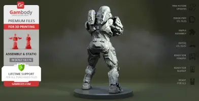
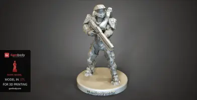
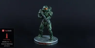
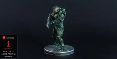
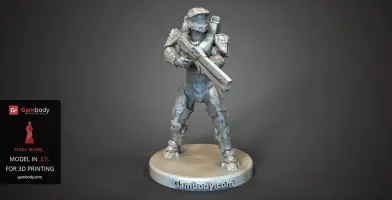
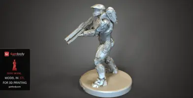
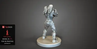
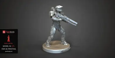
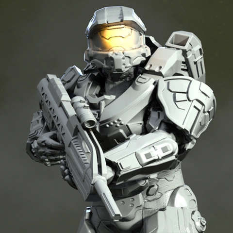
ABOUT THIS 3D MODEL
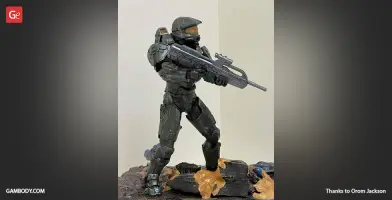
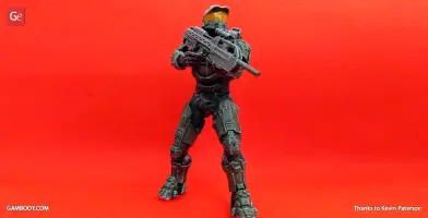
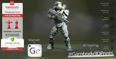
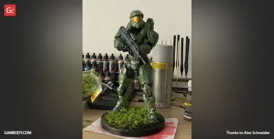
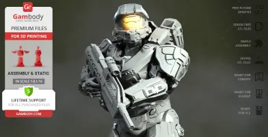
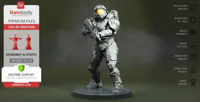
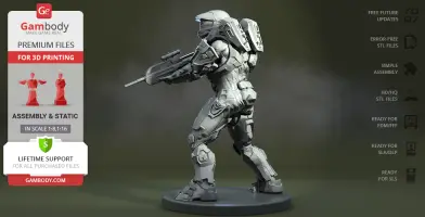
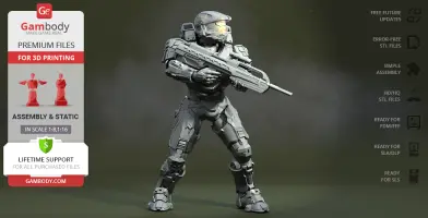
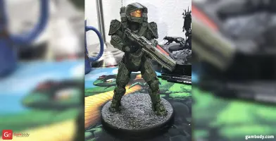
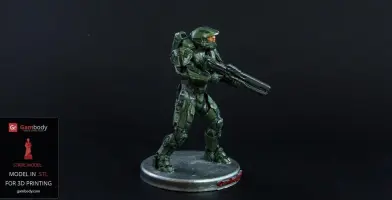
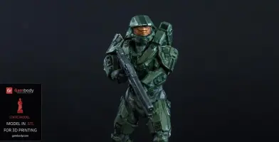
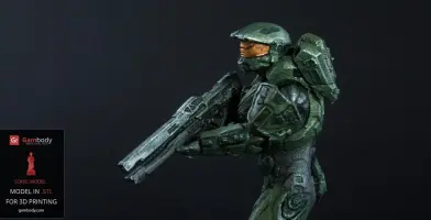
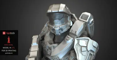
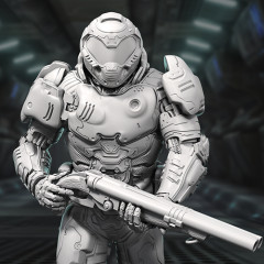
Master chief petty officer John 117 or simply Master Chief is the super soldier, the protagonist of the Halo franchise. During the first six years of his life, John lived with his parents on the human colony planet Eridanus II. But after the boy was conscripted into the military service John’s life and personality changed drastically. He became the SPARTAN-II Program recruit and later the soldier in the UNSC Naval Special Warfare Command. With over 30 years of military service experience, Master Chief is one of the most renowned war veterans.
ADAPTATION FOR 3D PRINTING
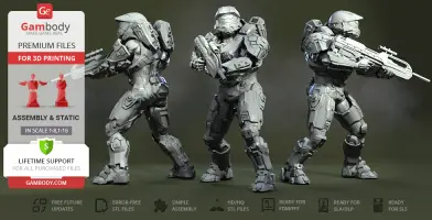
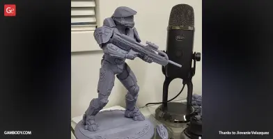
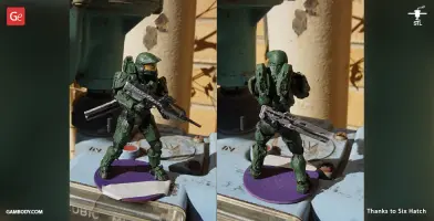
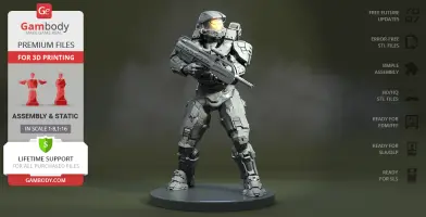
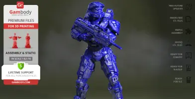
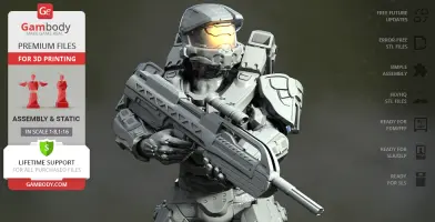
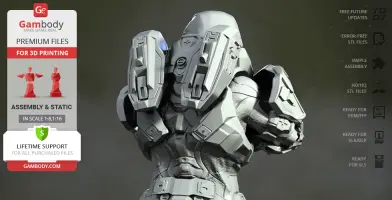
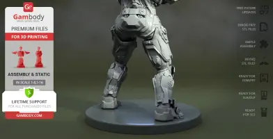
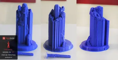
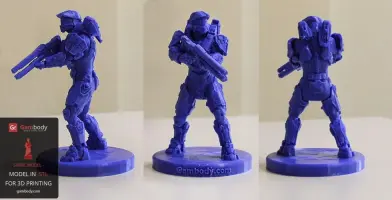
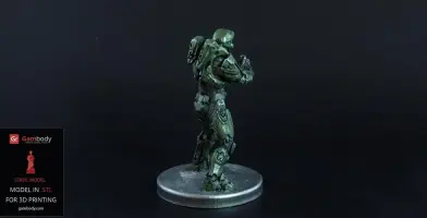
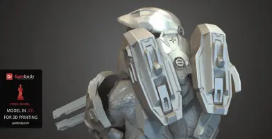
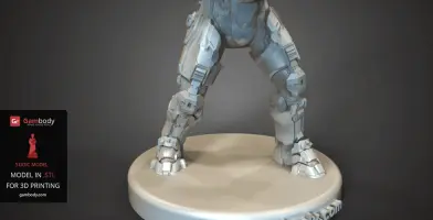
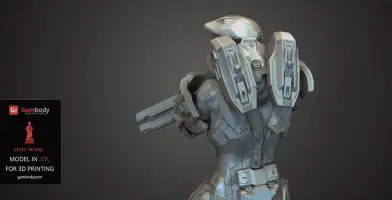
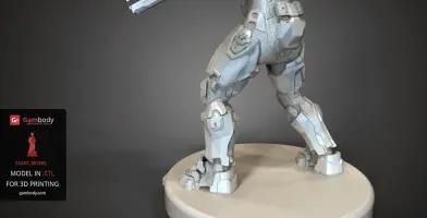
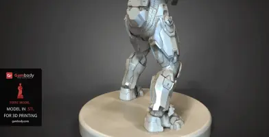
Master Chief 3D printing design is a static assembly model. The model’s cutting was chosen by our team to minimise the amount of generated support and some of the parts were hollowed out for you to save resin in the Eco version. In order to conceal the places where the assembly parts of the model are connected, Master Chief was cut along the contour of his armour. For you to achieve the cleanest 3D printed result, the character’s head, arms, legs, weapons etc. are provided as separate assembly parts.
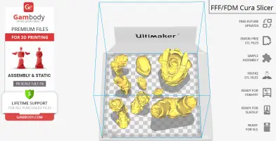
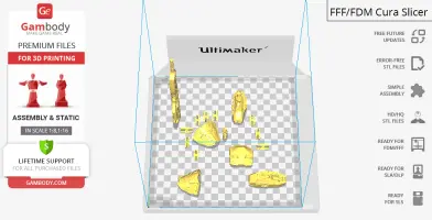
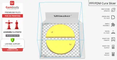
All assembly parts of the FFF/FDM versions come in STL files in recommended positions that were worked out in order to ensure the smoothness of the details’ surfaces after printing and so that the 3D printing beginners won't face difficulties when placing the parts on a build plate.
The design is saved in STL files, a format supported by most 3D printers. All STL files for 3D printing have been checked in Netfabb and no errors were shown.
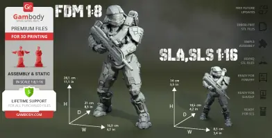
The 3D printing design's chosen scales are 1:8 for the FFF/FDM version and 1:16 for the DLP/SLA/SLS versions.
VERSIONS' SPECIFICATIONS
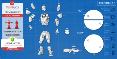
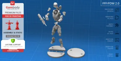
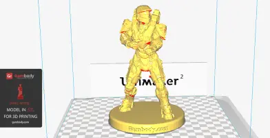
2.0 FFF/FDM version features:
- Contains 21 parts;
- A printed model is 281 mm tall, 169 mm wide, 210 mm deep
- Assembly kit includes locks. Lock (21_ge_lock_7S(x7)) needs to be printed 7 times. Lock (20_ge_lock_10H(x2)) needs to be printed twice;
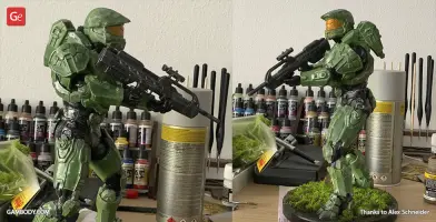
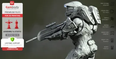
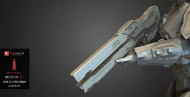
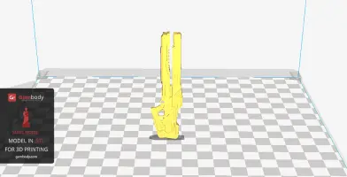
- Made with new Battle Rifle;
- All parts are divided in such a way that you will print them with the smallest number of support structures.
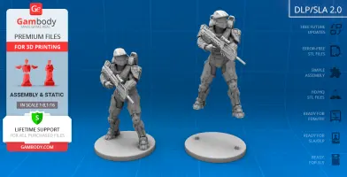
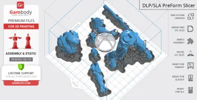
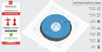
1.0 DLP/SLA version features:
- Contains 9 parts;
- A printed model is 140 mm tall, 85 mm wide, 105 mm deep;
- All parts are divided in such a way to fit the build plates and to ensure that support structures are generated where needed.
1.0 DLP/SLA Eco version features:
- Contains 9 parts;
- A printed model is 140 mm tall, 85 mm wide, 105 mm deep;
- Some parts are manually hollowed out to save resin.
1.0 DLP/SLA Pre-supported version features:
- Contains 9 parts;
- A printed model is 140 mm tall, 85 mm wide, 105 mm deep;
- The STL files that this version comprises are pre-supported, hollowed out, and have drain holes where needed;
- You may choose to print the STL files one by one or several at once, depending on the dimensions of your resin 3D printer's build plate;
- When slicing several STL files at once, the attachment layers (Platform Touch Shape) may overlap, but the supports must not come into contact.
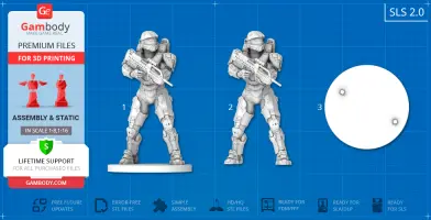
1.0 SLS version features:
- A printed model is 140 mm tall, 85 mm wide, 105 mm deep;
- Contains 1 part - solid Master Chief model.
1.0 FFF/FDM version features:
- Outdated version of the model;
- Contains 2 parts;
- A printed model is 160 mm tall, 105 mm wide, 109 mm deep;
- The scale of the model is indeterminate.
You can get the STL files of the Master Chief model right now! Just click the green Buy button in the top-right corner of the model’s page. You can pay with PayPal or your credit card.
Watch the tutorial on how to assemble the 3D Printed Master Chief model from the provided 3D Print Files at Gambody YouTube channel.
Also, you may like other Video Games 3D Printing Designs.
_______
FAQ:
Generic
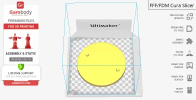
Below you can find printing recommendations for Cura, Simplify3D, Slic3r and PrusaSlicer software.
Cura printing recommendations:
These are basic settings that were tested in Cura 4.8.0 slicer.
The test models were printed on Ultimaker 2, Creality Ender 3, Creality CR-10S Pro V2, Anycubic I3 Mega, Anycubic I3 MegaS 3D printers with PLA and PETG filaments.
Disclaimer: The following printing settings are a recommendation, not an obligation. The parameters can vary depending on the peculiarities of your 3D printer, the material you use and especially the particular assembly part at hand. Each part that any model comprises often needs preliminary review and you are free to tweak the settings the way you find suitable.
Note:- You can scale up the model (downscaling is not recommended!);- All connectors should be printed at 100% Infill;- For all parts of locks (“ge_lock” in “Source files”) you need to change "Brim" type to "Skirt" in Build Plate Adhesion section.
QualityLayer Height: 0.12 mm (you can also set Layer Height at 0.16 or 0.2mm for 0.4mm nozzles)Initial Layer Height: 0.2 mm (carefully level the print bed and keep your Initial Layer Height the same as the main Layer Height)
Line Width: 0.4 mmWall Line Width: 0.4 mmOuter Wall Line Width: 0.4 mmInner Wall(s) Line Width: 0.4 mmTop/Bottom Line Width: 0.4 mmInfill Line Width: 0.4 mmSkirt/Brim Line Width: 0.4 mmSupport Line Width: 0.4 mm
Initial Layer Line Width: 100%
Shell Wall Thickness: 0.8 mmWall Line Count: 2
Outer Wall Wipe Distance: 0.3 mmTop Surface Skin Layers: 0Top/Bottom Thickness: 0.6 mmTop Thickness: 0.6 mmTop Layers: 5Bottom Thickness: 0.6 mmBottom Layers: 5Initial Bottom Layers: 5
Top/Bottom Pattern: LinesBottom Pattern Initial Layer: LinesTop/Bottom Line Directions: [ ]Outer Wall Inset: 0 mmOptimize Wall Printing Order: Check
Compensate Wall Overlaps: CheckCompensate Inner Wall Overlaps: Check
Minimum Wall Flow: 0%Fill Gaps Between Walls: EverywhereFilter Out Tiny Gaps: CheckHorizontal Expansion: 0 mmInitial Layer Horizontal Expansion: 0 mmHole horizontal expansion: 0
Z Seam Alignment: User SpecifiedZ Seam Position: BackZ Seam X: Average length of your printer’s plate (e.g.”150” if your plate is 300mm on the X-axis)Z Seam Y: A value higher than the length of your plate on the Y-axis (e.g. 700)
Seam Corner Preference: Hide SeamExtra Skin Wall Count: 1Skin Overlap Percentage: 10%Skin Overlap 0.04 mm
Infill Infill Density: 20% (for all smaller parts and for all parts of connectors use 100% Infill)Infill Pattern: TrianglesConnect Infill Lines: CheckInfill Line Directions: [ ]Infill X Offset: 0 mmInfill Y Offset: 0 mmInfill Line Multiplier: 1Extra Infill Wall Count: 0Infill Overlap Percentage: 10-20%Infill Overlap: 0.04 mmSkin Overlap Percentage: 5%Skin Overlap: 0.02 mmInfill Wipe Distance: 0 mmInfill Layer Thickness: 0.24 mmGradual Infill Steps: 0Infill Before Walls: CheckMinimum Infill Area: 0 mm2Skin Removal Width: 0.8 mmTop Skin Removal Width: 0.8 mmBottom Skin Removal Width: 0.8 mmSkin Expand Distance: 0.8Top Skin Expand Distance: 0.8Bottom Skin Expand Distance: 0.8Maximum Skin Angle for Expansion: 90˚Minimum Skin Width for Expansion: 0.0Skin Edge Support Thickness: 0Skin Edge Support Layers: 0
Material Initial Layer Flow: 100%Printing Temperature: See your filament settingsInitial Printing Temperature: Your filament settingsFinal Printing Temperature: Your filament settingsBuild Plate Temperature: Your filament settingsBuild Plate Temperature Initial Layer: Your filament settings + 5°Flow: 100% (Important! If you face difficulty printing the model, you may need to adjust the Flow parameter. You may research the topic using the Internet or seek assistance at our Customer Support Team at support@gambody.com)
Speed
You can increase the printing Speed by 20% when you print simple objects. For small/thin parts you need to decrease the Speed by 25% - 50%.
Print Speed: 50 mm/s Infill Speed: 50 mm/s Wall Speed: 25 mm/s Outer Wall Speed:25 mm/s Inner Wall Speed: 50 mm/sTop/Bottom Speed: 25mm/sSupport Speed: 25 mm/s Support Infill Speed: 45 mm/s Support Interface Speed: 25 mm/s Support Roof Speed: 25 mm/s Support Floor Speed: 25 mm/sTravel Speed: 80 mm/sInitial Layer Speed: 80 mm/sInitial Layer Print Speed: 20 mm/sInitial Layer Travel Speed: 80 mm/sSkirt/Brim Speed: 20 mm/sZ Hop Speed: 5 mm/sNumber of Slower Layers: 2Enable Acceleration Control: Check
When printing simple objects, you need to set all Acceleration parameters at 500 mm/s. For small/thin parts you need to decrease the Acceleration by 50% - 70%.
Travel Enable Retraction: CheckRetraction Distance: 4-8 mm, 1-3 mm for Direct Extruder (This is the most important retraction parameter. You can find your optimal value of Retraction Distance by printing any test object, e.g. bridges, towers etc.)Retraction Speed: 25mm/sRetraction Retract Speed: 25 mm/sRetraction Prime Speed: 25 mm/sRetraction Extra Prime Amount: 0 mm3 Retraction Minimum Travel: 1.5 mmMaximum Retraction Count: 100Minimum Extrusion Distance Window: 6,5 - 10 mmLimit Support Retractions: CheckCombing Mode: AllMax Comb Distance With No Retract: 30 mmRetract Before Outer Wall: CheckAvoid Printed Parts When Travelling: CheckAvoid Supports When Travelling: CheckTravel Avoid Distance: 1 mmLayer Start X: 0.0 mmLayer Start Y: 0.0 mmZ Hop When Retracted: CheckZ Hop Height: 0,3 mm
Cooling Enable Print Cooling: CheckFan Speed: 100%Regular Fan Speed: 100%Maximum Fan Speed: 100% Regular/Maximum Fan Speed Threshold: 10 sInitial Fan Speed: 0%Regular Fan Speed at Height: 0.36 mmRegular Fan Speed at Layer: 3 Minimum Layer Time: 10 sMinimum Speed: 10 mm/s
Support Generate Support: CheckSupport Structure: Normal (you can try using Tree Support Structure if you have difficulty printing any particular assembly part)Support Placement: Everywhere Support Overhang Angle: 60° (this parameter can range from 30° to 70° depending on the part at hand)Support Pattern: Zig ZagSupport Wall Line Count: 1 (stronger support that might be more difficult to remove) 0 (less strong support but is easier to remove)
Support Density: 15%Support Line Distance: 2.6667 mmInitial layer support line distance: 2.667 mm
Support Z Distance: 0.12 mmSupport Top Distance: 0.12 mmSupport Bottom Distance: 0.12 mmSupport X/Y Distance: 0.8-1 mmSupport Distance Priority: Z overrides X/YSupport Stair Step Height: 0.3 mmSupport Stair Step Maximum Width: 5.0 mmSupport Stair Step Minimum Slope Angle: 10°Support Join Distance: 2.0 mmSupport Horizontal Expansion: 0.2 mmSupport Infill Layer Thickness: 0.2 mmGradual Support Infill Steps: 0Minimum Support Area: 2 mmEnable Support Interface: Check (generates additional “pillow” on the support structure that leads to a more even surface, but can be difficult to remove in hard-to-reach areas)Enable Support Roof: CheckEnable Support Floor: CheckSupport Interface Thickness: 0.8 mmSupport Roof Thickness: 0.8 mmSupport Floor Thickness: 0.8 mmSupport Interface Resolution 0.2 mmSupport Interface Density: 50-100% Support Roof Density: 50-100%Support Roof Line Distance: 0.8 mm Support Floor Density: 50-100%Support Floor line Distance: 0.4mmSupport Interface Pattern: Grid Support Roof Pattern: Grid (this parameter should differ from Bottom Pattern Initial Layer in “Shell” section)Support Floor Pattern: GridMinimum Support Interface Area: 10mmMinimum Support Roof Area: 10 mmMinimum Support Floor Area: 10 mmSupport Interface Horizontal Expansion: 0.0 mmSupport Roof Horizontal Expansion: 0.0 mmSupport Floor Horizontal Expansion: 0.0 mmFan Speed Override: CheckSupported Skin Fan Speed: 100%Use Towers: CheckTower Diameter: 4 mmMinimum Diameter: 3.0 mmTower Roof Angle: 65°
Build Plate Adhesion Build Plate Adhesion Type: Skirt/Brim (For unsteady parts, and those parts that may come unstuck use “Brim”. For bigger assembly parts that have large adhesion area and for all parts of locks and claws that you want to come out clean use "Skirt")Skirt/Brim Minimum Length: 250 mmBrim Width: 8.0 mm Brim Line Count: 10Brim Only on Outside: Check
Mesh Fixes Union Overlapping Volumes: CheckMerged Meshes Overlap: 0.15 mm
Special ModesPrint Sequence: All at OnceSurface Mode: Normal
ExperimentalSlicing Tolerance: MiddleMaximum Resolution: 0.01 mmFlow rate compensation max extrusion offset: 0 mmFlow rate compensation factor: 100%
Simplify3D printing recommendations:
This model was tested with PLA material.
To avoid printing problems, we recommend the following settings:
ExtruderNozzle Diameter: 0.4 mmExtrusion Multiplier: 0.97Extrusion Width: Auto
Retraction Distance: 5.00 mmExtra Restart Distance: 0.00 mmRetraction Vertical Lift: 0.08 mmRetraction Speed: 5400.0 mm/min
Wipe Distance: 5.00 mm
LayerPrimary Layer Height: 0.2 mmTop Solid Layers: 8Bottom Solid Layers: 5Outline/Perimeter Shells: 2Outline Direction: Inside-Out
First Layer Height: 90%First Layer Width: 100%First Layer Speed: 20%
AdditionsUse Skirt/Brim: CheckSkirt Layers: 1Skirt Offset from Part: 6.00 mmSkirt Outlines: 5
InfillInternal Fill Pattern: Fast HoneycombExternal Fill Patern: RectilinearInterior Fill Percentage: 10%Outline Overlap: 22%Infill Extrusion Width: 100%Minimum Infill Length: 5.00 mmCombine Infill Every: 1 layers
External Infill Angle Offsets: 45/-45 deg
SupportGenerate Support Material: CheckSupport Infill Percentage: 15%Extra Inflation Distance: 1.00 mmSupport Base Layers: 0Combine Support Every: 1 layers
Dense Support Layers: 0Dense Infill Percentage: 70%
Support Type: NormalSupport Pillar Resolution: 5.00 mmMax Overhang Angle: 60 deg
Horizontal Offset From Part: 0.50 mmUpper Vertical Separation Layers: 1Lower Vertical Separation Layers: 1
Support Infill Angles: 45 deg
TemperatureExtruder 1 Temperature: 210Heated Bed: 60
CoolingIncrease fan speed for layers below: 45.0 sec Maximum Cooling fan speed: 50%Bridging fan speed override: 100%
SpeedsDefault Printing Speed: 4800.0 mm/minOutline Underspeed: 50%Solid Infill Underspeed: 80%Support Structure Underspeed: 80%X/Y Axis Movement Speed: 10800.0 mm/minZ Axis Movemen Speed: 1002.0 mm/min
Adjust printing speed for layers below: 15.0 sec Allow speed reduction down to: 20%
OtherUnsupported area threshold: 20.0 sq m
Slic3r printing recommendations:
These basic 3D printing settings recommendations for beginners were tested in Slic3r 1.3.0 software. Test models were printed on Ultimaker 2, Creality Ender 3, Creality Cr-10S pro v2, Anycubic I3 Mega, Anycubic I3 MegaS, Anycubic Vyper with PLA and PetG filaments. Note:
- You can upscale your 3D printing models. Downscaling is not recommended - it can make smaller parts of the model unprintable, distort the model’s level of detail and result in assembly issues. - All connectors should be printed at 100% Infill.- When printing Lock connectors, we recommend setting the “Brim width” parameter to 0 in the "Skirt and Brim" print settings. In that way, the Locks will be 3D printed with a Skirt only.
PrusaSlicer printing recommendations:


Comments