


This should take overall.

This 3D Model consists of files in StereoLithography (.Stl) format that is optimized for 3D printing.
Before printing the files, we strongly recommend reading the PRINTING DETAILS section.
Hyperion M-03 3D Printing Model comes in 1 version for FFF/FDM 3D printers. STL files of the version are available for download after the purchase.
Detailed information about this 3D printing model is available in the DESCRIPTION section.

|
|||||
|---|---|---|---|---|---|
| File Name | File Size | Time / Filament | Object Size (x/y/z mm) |
||
|
1_mod1_ball_joint (repair ed).stl |
0.54 MiB | 5 min <1 m | 6 x 6 x 12 | Download | |
|
2_mod1_beak (repaired).st l |
0.14 MiB | 32 min <1 m | 16 x 11 x 26 | Download | |
|
3_mod1_cabine (repaired). stl |
1.24 MiB | 26 min <1 m | 12 x 19 x 26 | Download | |
|
4_mod1_frame_2 (repaired) .stl |
0.59 MiB | 27 min <1 m | 17 x 7 x 23 | Download | |
|
5_mod1_frame_3_x2 (repair ed).stl |
0.23 MiB | 16 min <1 m | 18 x 6 x 18 | Download | |
|
6_mod1_frame_mod_1 (repai red).stl |
1.24 MiB | 2 h 12 min 1 m | 30 x 31 x 47 | Download | |
|
7_mod1_head_1 (repaired). stl |
4.26 MiB | 37 min <1 m | 22 x 16 x 22 | Download | |
|
8_mod1_head_2 (repaired). stl |
2.56 MiB | 2 h 2 min 1 m | 37 x 45 x 26 | Download | |
|
9_mod1_joint_1 (repaired) .stl |
1.37 MiB | 14 min <1 m | 9 x 10 x 15 | Download | |
|
10_mod1_neck (repaired).s tl |
0.47 MiB | 26 min <1 m | 15 x 9 x 22 | Download | |
|
11_mod1_prop_mod_1_L (rep aired).stl |
4.29 MiB | 1 h 46 min 1 m | 49 x 14 x 61 | Download | |
|
12_mod1_prop_mod_2_R (rep aired).stl |
4.28 MiB | 1 h 49 min 1 m | 49 x 14 x 61 | Download | |
|
13_mod2_arm_1_ x2 (repair ed).stl |
3.67 MiB | 1 h 55 min 1 m | 28 x 36 x 20 | Download | |
|
14_mod2_arm_2_x2 (repaire d).stl |
1.21 MiB | 40 min <1 m | 14 x 23 x 14 | Download | |
|
15_mod2_arm_3_x2 (repaire d).stl |
1.66 MiB | 1 h 4 min 1 m | 15 x 36 x 35 | Download | |
|
16_mod2_arm_4_x2 (repaire d).stl |
1.50 MiB | 31 min <1 m | 14 x 16 x 15 | Download | |
|
17_mod2_beak (repaired).s tl |
2.14 MiB | 1 h 28 min 1 m | 32 x 23 x 50 | Download | |
|
18_mod2_elbow_x2_ABS (rep aired).stl |
0.04 MiB | 37 min <1 m | 14 x 27 x 22 | Download | |
|
19_mod2_finger_L_x4 (repa ired).stl |
0.25 MiB | 3 min <1 m | 11 x 8 x 2 | Download | |
|
20_mod2_finger_R_x4 (repa ired).stl |
0.25 MiB | 3 min <1 m | 11 x 8 x 2 | Download | |
|
21_mod2_hand_L (repaired) .stl |
1.43 MiB | 21 min <1 m | 12 x 17 x 14 | Download | |
|
22_mod2_hand_R (repaired) .stl |
1.44 MiB | 21 min <1 m | 12 x 17 x 14 | Download | |
|
23_mod2_joint_ball (repai red).stl |
0.64 MiB | 14 min <1 m | 9 x 10 x 16 | Download | |
|
24_mod2_joint_beak (repai red).stl |
0.25 MiB | 27 min <1 m | 13 x 30 x 16 | Download | |
|
25_mod2_joint_shoulder_1_ x2_ABS (repaired).stl |
1.19 MiB | 27 min <1 m | 9 x 19 x 14 | Download | |
|
26_mod2_joint_shoulder_2_ x2_ABS (repaired).stl |
0.59 MiB | 22 min <1 m | 11 x 18 x 15 | Download | |
|
27_mod2_joint_shoulder_3_ x2_ABS (repaired).stl |
0.58 MiB | 14 min <1 m | 22 x 10 x 9 | Download | |
|
28_mod2_body (repaired).s tl |
12.72 MiB | 7 h 23 min 4 m | 56 x 42 x 59 | Download | |
|
29_mod2_prop_mod_2_L (rep aired).stl |
5.54 MiB | 1 h 37 min 1 m | 24 x 32 x 34 | Download | |
|
30_mod2_prop_mod_2_R (rep aired).stl |
5.54 MiB | 1 h 40 min 1 m | 24 x 32 x 34 | Download | |
|
31_mod2_shoulder_x2 (repa ired).stl |
1.75 MiB | 1 h 26 min 1 m | 35 x 26 x 26 | Download | |
|
32_mod2_wing_no_support_L (repaired).stl |
2.51 MiB | 58 min 1 m | 70 x 62 x 6 | Download | |
|
33_mod2_wing_no_support_R (repaired).stl |
2.51 MiB | 58 min 1 m | 70 x 62 x 6 | Download | |
|
34_mod2_wing_with_support _L (repaired).stl |
2.50 MiB | 1 h 32 min 1 m | 70 x 63 x 6 | Download | |
|
35_mod2_wing_with_support _R (repaired).stl |
2.50 MiB | 1 h 32 min 1 m | 70 x 63 x 6 | Download | |
|
36_mod3_cannon_2 (repaire d).stl |
2.30 MiB | 1 h 14 min 1 m | 32 x 44 x 14 | Download | |
|
37_mod3_cannon_3 (repaire d).stl |
0.14 MiB | 23 min <1 m | 7 x 46 x 7 | Download | |
|
38_mod3_cat_x44 (repaired ).stl |
0.16 MiB | 10 min <1 m | 16 x 5 x 10 | Download | |
|
39_mod3_central_foot_L_AB S (repaired).stl |
0.90 MiB | 52 min <1 m | 15 x 23 x 27 | Download | |
|
40_mod3_central_foot_R_AB S (repaired).stl |
0.89 MiB | 52 min <1 m | 15 x 23 x 27 | Download | |
|
41_mod3_foot x2 (repaired ).stl |
0.34 MiB | 33 min <1 m | 18 x 14 x 26 | Download | |
|
42_mod3_foot_joint_x2 (re paired).stl |
0.60 MiB | 8 min <1 m | 7 x 15 x 7 | Download | |
|
43_mod3_foot_up_x2 (repai red).stl |
0.21 MiB | 14 min <1 m | 15 x 21 x 10 | Download | |
|
44_mod3_heel_L_tallone_2 (repaired).stl |
0.29 MiB | 16 min <1 m | 18 x 12 x 10 | Download | |
|
45_mod3_heel_R_tallone_1 (repaired).stl |
0.22 MiB | 17 min <1 m | 15 x 12 x 10 | Download | |
|
46_mod3_hip_1_no_support _x2_ABS (repaired).stl |
0.82 MiB | 23 min <1 m | 24 x 16 x 13 | Download | |
|
47_mod3_hip_1_with_suppor t _x2_ABS (repaired).stl |
0.65 MiB | 25 min <1 m | 23 x 16 x 13 | Download | |
|
48_mod3_hip_2_x2_ABS (rep aired).stl |
1.01 MiB | 14 min <1 m | 17 x 25 x 7 | Download | |
|
49_mod3_hip_3_x2_ABS (rep aired).stl |
0.29 MiB | 13 min <1 m | 16 x 16 x 11 | Download | |
|
50_mod3_hip_decor_L (repa ired).stl |
1.66 MiB | 1 h 2 min 1 m | 20 x 21 x 32 | Download | |
|
51_mod3_hip_decor_R (repa ired).stl |
1.66 MiB | 1 h 2 min 1 m | 20 x 21 x 32 | Download | |
|
52_mod3_hip_decor_x2 (rep aired).stl |
0.07 MiB | 22 min <1 m | 7 x 25 x 15 | Download | |
|
53_mod3_knee_1_x2 (repair ed).stl |
0.31 MiB | 1 h 2 min 1 m | 27 x 38 x 18 | Download | |
|
54_mod3_knee_2_x2_ABS (re paired).stl |
0.17 MiB | 11 min <1 m | 6 x 26 x 8 | Download | |
|
55_mod3_knee_joint_x2_ABS (repaired).stl |
0.03 MiB | 18 min <1 m | 6 x 32 x 10 | Download | |
|
56_mod3_leg_1_L (repaired ).stl |
1.63 MiB | 4 h 7 min 2 m | 30 x 34 x 80 | Download | |
|
57_mod3_leg_1_R (repaired ).stl |
1.63 MiB | 4 h 7 min 2 m | 30 x 34 x 80 | Download | |
|
58_mod3_leg_2_L (repaired ).stl |
0.74 MiB | 1 h 14 min 1 m | 9 x 79 x 29 | Download | |
|
59_mod3_leg_2_R (repaired ).stl |
0.74 MiB | 1 h 15 min 1 m | 9 x 79 x 29 | Download | |
|
60_mod3_pelvis_1 (repaire d).stl |
2.88 MiB | 3 h 12 min 2 m | 44 x 33 x 33 | Download | |
|
61_mod3_pelvis_2 (repaire d).stl |
0.11 MiB | 21 min <1 m | 13 x 23 x 15 | Download | |
|
62_mod3_pelvis_3 (repaire d).stl |
0.13 MiB | 28 min <1 m | 11 x 23 x 18 | Download | |
|
63_mod3_skirt_front_1_ABS (repaired).stl |
0.10 MiB | 37 min <1 m | 19 x 30 x 14 | Download | |
|
64_mod3_skirt_front_2_ABS (repaired).stl |
0.11 MiB | 36 min <1 m | 19 x 30 x 14 | Download | |
|
65_mod3_skirt_front_3_ABS (repaired).stl |
0.02 MiB | 8 min <1 m | 13 x 16 x 5 | Download | |
|
66_mod3_skirt_front_4_ABS (repaired).stl |
0.02 MiB | 8 min <1 m | 13 x 16 x 5 | Download | |
|
67_mod3_skirt_rear_1_ABS (repaired).stl |
0.11 MiB | 34 min <1 m | 19 x 26 x 14 | Download | |
|
68_mod3_skirt_rear_2_ABS (repaired).stl |
0.11 MiB | 34 min <1 m | 19 x 26 x 14 | Download | |
|
69_mod3_skirt_rear_3_ABS (repaired).stl |
0.02 MiB | 8 min <1 m | 13 x 13 x 5 | Download | |
|
70_mod3_skirt_rear_4_ABS (repaired).stl |
0.02 MiB | 8 min <1 m | 13 x 13 x 5 | Download | |
|
71_mod3_skirt_side_1 (rep aired).stl |
2.03 MiB | 31 min <1 m | 11 x 19 x 17 | Download | |
|
72_mod3_skirt_side_2 (rep aired).stl |
2.03 MiB | 32 min <1 m | 11 x 19 x 17 | Download | |
|
73_mod3_wheel_x8 (repaire d).stl |
0.10 MiB | 25 min <1 m | 11 x 14 x 14 | Download | |
|
Keychain (repaired).stl |
0.35 MiB | 23 min <1 m | 30 x 30 x 2 | Download | |
|
Tag (repaired).stl |
1.70 MiB | 1 h 16 min 1 m | 150 x 18 x 5 | Download | |
| ... | |||||
This should take overall.
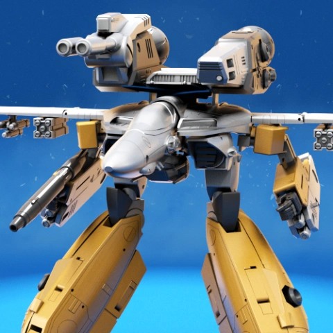
ABOUT THIS 3D MODEL
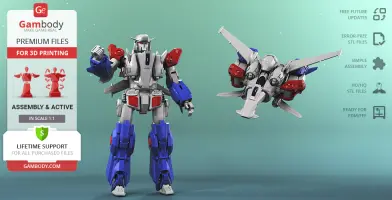
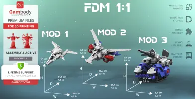
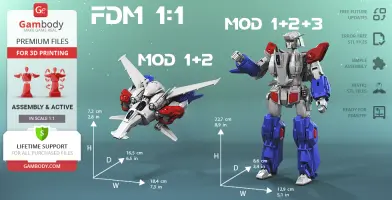
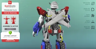
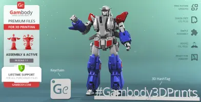
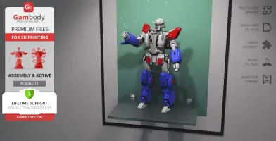
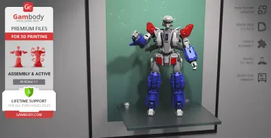
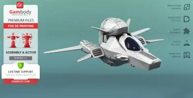
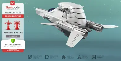
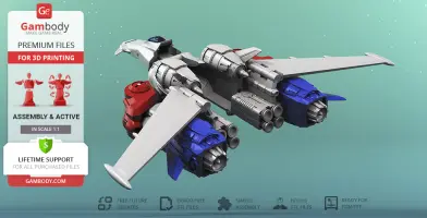
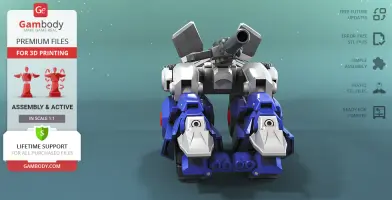
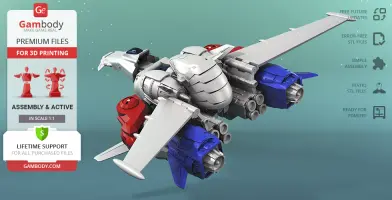
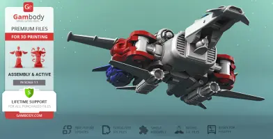
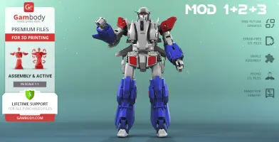
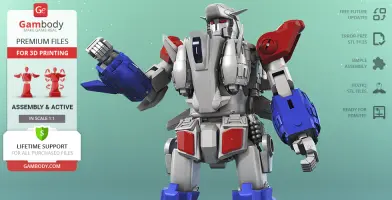
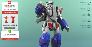
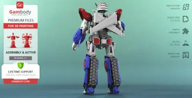
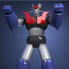
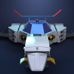
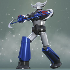
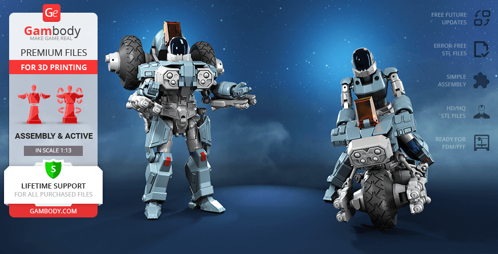
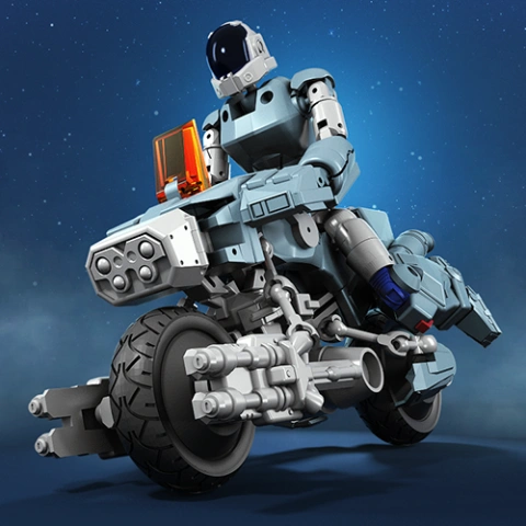
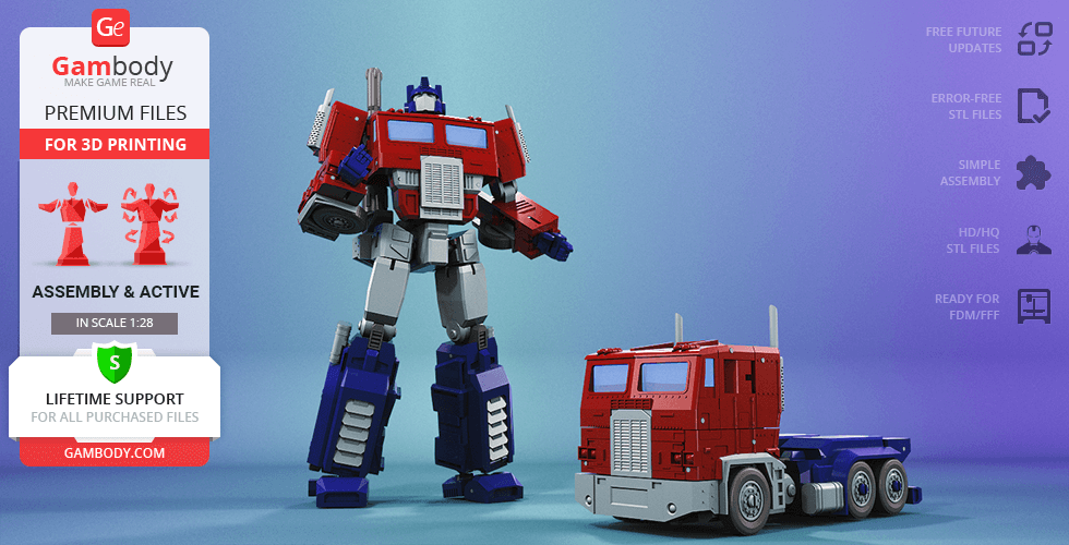
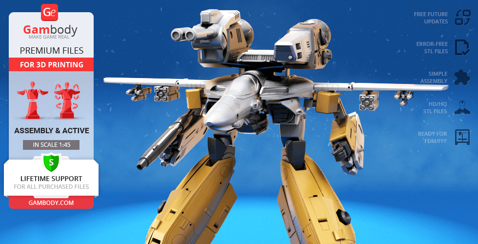
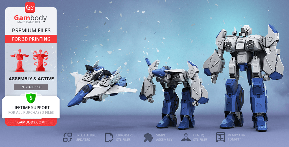
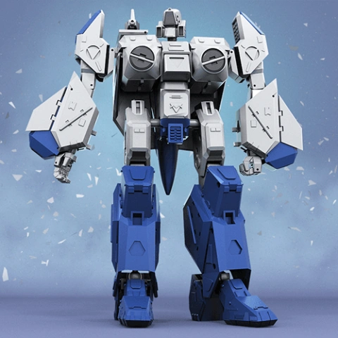
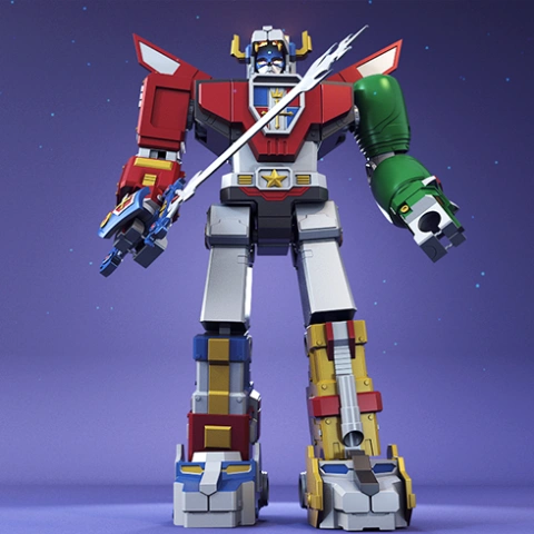
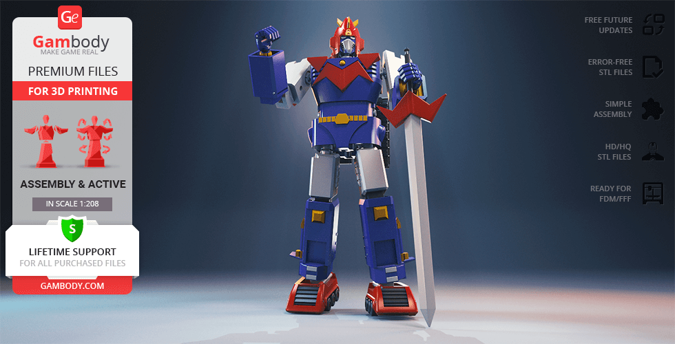
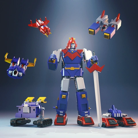
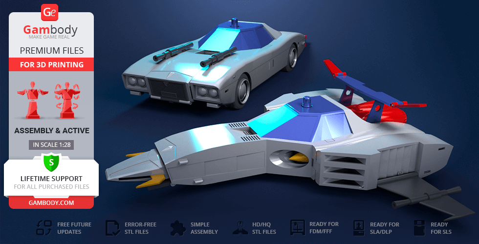
Giant humanoid mobile robots, also known as “mechas”, owe their origins to Japanese anime and manga that spawned an infinite universe of powerful machines deployed to defend Earth from all kinds of threats. Our talented contributing 3D artist came up with his own version of such mecha, having designed Hyperion M-03 - the original modular robot for 3D printing. The author of the model mentioned that the design of his mecha was chiefly inspired by the legendary Japanese Gundam series and the Gunpla kits ("Gundam plastic model" kits) that have been incredibly popular among robot anime fans and model kits enthusiasts since the 1980s. Hyperion M-03 is a skilfully engineered transformable robot that primarily consists of three vehicles - two aircraft and an assault tank. The two aircraft modules significantly differ in size and when joined together form a considerably bigger Super Aircraft. The Assault Tank part is designed with multi-section caterpillar tracks that are fully articulated and ensure the forward movement of the module. While each of the robot’s mods is pretty fascinating and functional alone, here comes the coolest part - thanks to the articulated interlocking mechanisms introduced by the author of the model you can combine all three vehicles to create the awesome humanoid Hyperion M-03! The whole project took the 3D artist circa 200 hours to fulfill and now any Gunpla or Transformers enthusiast has an incredible opportunity to 3D print, assemble and transform one’s very own humanoid mecha!
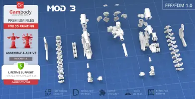
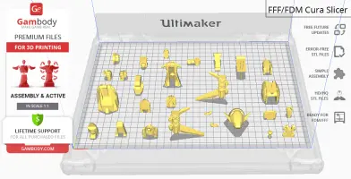
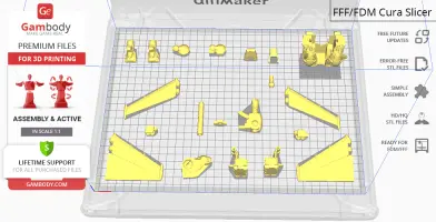
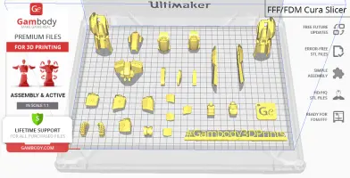
ADAPTATION FOR 3D PRINTING
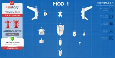
Hyperion M-03 model for 3D printing is a highly articulated assembly model and its moderation took Gambody team 35 hours in total. In order to ensure the articulation and transformation of the modular robot between its modules, Hyperion M-03 was divided into many assembly parts. For you to switch both assembled Aircraft and Assault Tank modules between Super Aircraft and Hyperion M-03 all model’s joints were designed to presuppose the introduction of articulated interlocking mechanisms. All the assembly parts are provided in STL files in recommended positions that were worked out in order to ensure the smoothness of details’ surfaces after printing and so that the 3D printing beginners won't face difficulties when placing the parts on a build plate. The mecha can be assembled without glue or screws but you will need additional “pins” to secure the parts. These pins do not come in STL files but can be made out of short pieces of regular 1.75 PLA (watch the "Assembly video" to see the pins coloured red). Make sure to watch "Assembly video" in the photo preview section till the end where you can also see the modules transform into Super Aircraft and Hyperion M-03. When downloading any model's file you will also receive "Assembly Manual" for FFF/FDM 1.0 version in PDF format.
The model is saved in STL files, a format supported by most 3D printers. All STL files for 3D printing have been checked in Netfabb and no errors were shown.
VERSION SPECIFICATIONS
FFF/FDM 1.0 version features:
- Contains 73 parts that comprise 3 modules of the mecha;
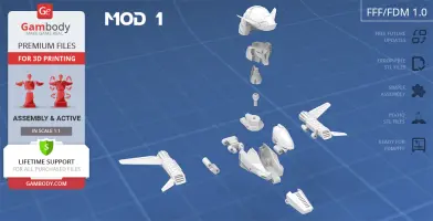
- When printed First Aircraft (MOD 1) stands 44 mm tall, 120 mm wide, 111 mm deep;
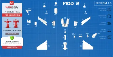
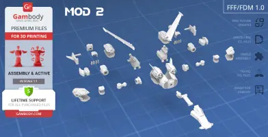
- Second Aircraft (MOD 2) is 43 mm tall, 187 mm wide, 165 mm deep;
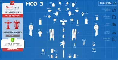
- Assault Tank (MOD 3) is 90 mm tall, 81 mm wide, 156 mm deep;
- Assembled First and Second Aircraft (MOD 1 + MOD 2) form Super Aircraft that is 72 mm tall, 184 mm wide, 165 mm deep;
- All three vehicles combined (MOD 1 + MOD 2 + MOD 3) form Hyperion M-03 that stands 227 mm tall, 129 mm wide, 86 mm deep;
- Each robot’s joint is articulated and all assembly parts are interlocking which allows the model's transformation;
- We recommend that you watch the "Assembly video" till the end to see the modules transform into Super Aircraft and Hyperion M-03;
Important notes from the author of the model:
- The assembly of the model requires additional “pins” that can be made out of short pieces of regular 1.75 PLA - watch the "Assembly video" to see the pins coloured red;
- There are some assembly parts that need to be printed multiple times - the number of required copies (x2, x4 etc.) is indicated in the title of the file in "Source files", e.g. file "5_mod1_frame_3_x2" needs to be printed 2 times;
- Parts "mod2_wing_L", "mod2_wing_R" and "mod3_hip_1" also come in alternative pre-supported variants (files 34, 35 and 47, "with support" in the title);
- The titles of some assembly parts in "Source files" tab suggest that you print them using ABS, e.g. 18_mod2_elbow_x2_ABS;
- The author of the model recommends that you print those parts in ABS that will provide proper friction, better resistance and ensure excellent articulation and durability;
- Alternatively, you can stick to PLA (or PLA+) and apply a couple of coats of any nail polish to all movable parts (that have "ABS" in the title) in order to ensure needed friction.
WHAT WILL YOU GET AFTER PURCHASE?
- STL files of Hyperion M-03 Model for 3D printing which consist of 73 parts;
- 1 version of files for this model for FFF/FDM;
- High-poly detailed model of Hyperion M-03;
- Assembly Manual for FFF/FDM 1.0 version in PDF format;
- Detailed settings that we provide as a recommendation for Cura , Simplify3D and Slic3r for the best print;
- Full technical support from the Gambody Support Team.
You can get the model of Hyperion M-03 for 3D Printing immediately after the purchase! Just click the green Buy button in the top-right corner of the model’s page. You can pay with PayPal or your credit card.
Watch the tutorial on how to assemble Hyperion M-03 3D Printing Model at Gambody YouTube channel.
Also, you may like other Robot 3D Printing Models, as well as Robotech Models for 3D Printing and Anime 3D Printing Figurines.
_______
FAQ:
Where can I print a model if I have no printer?
How to get started with 3D printing?
How to set up my 3D printer?
How to choose right 3D model print bed positioning?
How to paint printed figurine?
This model was tested in Cura 3.4.1 and printed on an Ultimaker 2 in PLA material. Below you can find printing recommendations for Cura, Simplify3D and Slic3r softwares.
Recommendations: Use ABS or PLA Plus filament to print more durable and friction resistant details.
To avoid printing problems, we recommend the following settings:
Quality
Layer Height: 0.1 mm
Initial Layer Height: 0.3 mm
Line Width: 0.4 mm
Wall Line Width: 0.4 mm
Outer Wall Line Width: 0.4 mm
Inner Wall(s) Line Width: 0.4 mm
Top/Bottom Line Width: 0.4 mm
Infill Line Width: 0.4 mm
Skirt/Brim Line Width: 0.4 mm
Support Line Width: 0.4 mm
Initial Layer Line Width: 100%
Shell
Wall Thickness: 0.8 mm
Wall Line Count: 2
Outer Wall Wipe Distance: 0.2 mm
Top Surface Skin Layers: 0
Top/Bottom Thickness: 0.8 mm
Top Thickness: 0.8 mm
Top Layers: 8
Bottom Thickness: 0.8 mm
Bottom Layers: 8
Top/Bottom Pattern: Lines
Bottom Pattern Initial Layer: Lines
Top/Bottom Line Directions: [ ]
Outer Wall Inset: 0 mm
Compensate Wall Overlaps: Check
Compensate Outer Wall Overlaps: Check
Compensate Inner Wall Overlaps: Check
Fill Gaps Between Walls: Everywhere
Filter Out Tiny Gaps: Check
Horizontal Expansion: 0 mm
Initial Layer Horizontal Expansion: 0 mm
Z Seam Alignment: Sharpest Corner
Seam Corner Preference: Hide Seam
Ignore Small Z Gaps: Check
Extra Skin Wall Count: 1
Infill
Infill Density: 80%
Infill Line Distance: 4.0 mm
Infill Pattern: Grid
Infill Line Directions: [ ]
Infill X Offset: 0 mm
Infill Y Offset: 0 mm
Infill Overlap Percentage: 10%
Infill Overlap: 0.04 mm
Skin Overlap Percentage: 5%
Skin Overlap: 0.02 mm
Infill Wipe Distance: 0.1 mm
Infill Layer Thickness: 0.1 mm
Gradual Infill Steps: 1
Gradual Infill Steps Height: 1.5 mm
Infill Before Walls: Check
Minimum Infill Area: 0 mm2
Skin Removal Width: 0.8 mm
Top Skin Removal Width: 0.8 mm
Bottom Skin Removal Width: 0.8 mm
Skin Expand Distance: 0.8
Top Skin Expand Distance: 0.8
Bottom Skin Expand Distance: 0.8
Maximum Skin Angle for Expansion: 90˚
Minimum Skin Width for Expansion: 0.0
Material
Initial Layer Flow: 100%
Enable Retraction: Check
Retraction Extra Prime Amount: 0 mm3
Retraction Minimum Travel: 0.8 mm
Maximum Retraction Count: 90
Minimum Extrusion Distance Window: 6.5 mm
Nozzle Switch Retraction Distance: 16 mm
Nozzle Switch Retraction Speed: 20 mm/s
Nozzle Switch Retract Speed: 20 mm/s
Nozzle Switch Prime Speed: 20 mm/s
Speed
Print Speed: 45 mm/s
Infill Speed: 45 mm/s
Wall Speed: 22.5 mm/s
Outer Wall Speed: 22.5 mm/s
Inner Wall Speed: 45 mm/s
Top/Bottom Speed: 15 mm/s
Travel Speed: 45 mm/s
Initial Layer Speed: 22.5 mm/s
Initial Layer Print Speed: 22.5 mm/s
Initial Layer Travel Speed: 30 mm/s
Skirt/Brim Speed: 30 mm/s
Maximum Z Speed: 0 mm/s
Number of Slower Layers: 2
Travel
Combing Mode: All
Avoid Printed Parts when Traveling: Check
Travel Avoid Distance: 0.625 mm
Layer Start X: 0.0 mm
Layer Start Y: 0.0 mm
Cooling
Enable Print Cooling: Check
Fan Speed: 100%
Regular Fan Speed: 100%
Maximum Fan Speed: 100%
Regular/Maximum Fan Speed Threshold: 10 s
Initial Fan Speed: 0%
Regular Fan Speed at Height: 0.3 mm
Regular Fan Speed at Layer: 2
Minimum Layer Time: 5 s
Minimum Speed: 10 mm/s
Support
Generate Support: Check
Support Placement: Everywhere
Support Overhang Angle: 50°
Support Pattern: Zig Zag
Connect Support ZigZags: Check
Support Density: 15 %
Support Line Distance: 3 mm
Support Z Distance: 0.1 mm
Support Top Distance: 0.1 mm
Support Bottom Distance: 0.1 mm
Support X/Y Distance: 1 mm
Support Distance Priority: Z overrides X/Y
Minimum Support X/Y Distance: 0.25 mm
Support Stair Step Height: 0.3 mm
Support Stair Step Maximum Width: 5.0 mm
Support Join Distance: 2.0 mm
Support Horizontal Expansion: 0.2 mm
Support Infill Layer Thickness: 0.1 mm
Gradual Support Infill Steps: 0
Use Towers: Check
Tower Diameter: 3.0 mm
Minimum Diameter: 3.0 mm
Tower Roof Angle: 65°
Build Plate Adhesion
Build Plate Adhesion Type: Brim (for all parts of locks use "Skirt")
Skirt/Brim Minimum Length: 250 mm
Brim Width: 8.0 mm
Brim Line Count: 18
Brim Only on Outside: Check
Mesh Fixes
Union Overlapping Volumes: Check
Merged Meshes Overlap: 0.15 mm
Special Modes
Print Sequence: All at Once
Surface Mode: Normal
Experimental
Slicing Tolerance: Middle
Maximum Resolution: 0.01 mm
Flow rate compensation max extrusion offset: 0 mm
Flow rate compensation factor: 100%
Disclaimer: This model will look outstanding if printed on SLA/SLS 3D printer. The accuracy of the model printed on FFF printer can vary from the result shown in the pictures.
This model was tested with PLA material.
To avoid printing problems, we recommend the following settings:
Extruder
Nozzle Diameter: 0.4 mm
Extrusion Multiplier: 0.97
Extrusion Width: Auto
Retraction Distance: 5.00 mm
Extra Restart Distance: 0.00 mm
Retraction Vertical Lift: 0.08 mm
Retraction Speed: 5400.0 mm/min
Wipe Distance: 5.00 mm
Layer
Primary Layer Height: 0.2 mm
Top Solid Layers: 8
Bottom Solid Layers: 5
Outline/Perimeter Shells: 2
Outline Direction: Inside-Out
First Layer Height: 90%
First Layer Width: 100%
First Layer Speed: 20%
Additions
Use Skirt/Brim: Check
Skirt Layers: 1
Skirt Offset from Part: 6.00 mm
Skirt Outlines: 5
Infill
Internal Fill Pattern: Fast Honeycomb
External Fill Patern: Rectilinear
Interior Fill Percentage: 80%
Outline Overlap: 22%
Infill Extrusion Width: 100%
Minimum Infill Length: 5.00 mm
Combine Infill Every: 1 layers
External Infill Angle Offsets: 45/-45 deg
Support
Generate Support Material: Check
Support Infill Percentage: 15%
Extra Inflation Distance: 1.00 mm
Support Base Layers: 0
Combine Support Every: 1 layers
Dense Support Layers: 0
Dense Infill Percentage: 70%
Support Type: Normal
Support Pillar Resolution: 5.00 mm
Max Overhang Angle: 60 deg
Horizontal Offset From Part: 0.50 mm
Upper Vertical Separation Layers: 1
Lower Vertical Separation Layers: 1
Support Infill Angles: 45 deg
Temperature
Extruder 1 Temperature: 210
Heated Bed: 60
Cooling
Increase fan speed for layers below: 45.0 sec
Maximum Cooling fan speed: 50%
Bridging fan speed override: 100%
Speeds
Default Printing Speed: 4800.0 mm/min
Outline Underspeed: 50%
Solid Infill Underspeed: 80%
Support Structure Underspeed: 80%
X/Y Axis Movement Speed: 10800.0 mm/min
Z Axis Movemen Speed: 1002.0 mm/min
Adjust printing speed for layers below: 15.0 sec
Allow speed reduction down to: 20%
Other
Unsupported area threshold: 20.0 sq m
Layer height
Layer height: 0.1 mm
First layer height: 90%
Vertical shells
Perimeters: 2
Horizontal shells
Soid layers:
Top: 8
Bottom: 5
Quality
Detect thin walls: Check
Detect bridging perimeters: Check
Advanced
Seam position: Random
Infill
Fill density: 80%
Fill pattern: Honeycomb
Top/bottom fill pattern: Rectilinear
Reducing printing time
Combine infill every: 1 layers
Advanced
Solid infill every: 0 layers
Fill angle: 25 deg
Solid infill threshold area: 0mm
Skirt
Loops: 2
Distance from object: 6 mm
Skirt height: 1 layers
Minimum extrusion length: 4 mm
Brim
Brim width: 10 mm
Support material
Generate support material: Check
Overhang threshold: 45 deg
Enforce support for the first: 3 layers
Raft
Raft layers: 0 layers
Options for support material and raft
Contact Z distance: 0.1 mm
Pattern: Rectilinear
Patter spacing: 2 mm
Pattern angle: 0 deg
Interface layers: 2 layers
Interface pattern spacing: 0.2 mm
Speed for print moves
Perimeters: 60 mm/s
Small perimeters: 20 mm/s
External perimeters: 20 mm/s
Infill: 60 mm/s
Solid infill: 60 mm/s
Top solid infill: 30 mm/s
Support material: 50 mm/s
Support material interface: 100%
Bridges: 30 mm/s
Gap fill: 50 mm/s
Speed for non-print moves
Travel: 60 mm/s
Modifiers
First layer speed: 30 mm/s
Acceleration control
Perimeters: 800 mm/s
Infill: 1500 mm/s
Bridge: 1000 mm/s
First layer: 1000 mm/s
Default: 1000 mm/s
Autospeed
Max print speed: 100 mm/s
Max volumetrix speed: 0 mm/s
Extrusion width
Default extrusion width: 0.42 mm
First layer: 0.42 mm
Perimeters: 0.42 mm
External perimeters: 0.42 mm
Infill: 0.42 mm
Solid infill: 0.42 mm
Top solid infill: 0.42 mm
Support material: 0.42 mm
Overlap
Infill/Perimeters overlap: 20%
Flow
Bridge flow ratio: 0.95
Other
XY Size Compensation: 0 mm
Threds: 8
Resolution: 0 mm
robot, robots, mech, space, action, vehicle, toy, mecha, tank, transformers, war, articulated, super-robot, assault, aircraft, weapons, gunpla, posable, anime, 16.74, october
You are about to report Hyperion M-03 3D Printing Model | Assembly + Action for violating our Terms and Conditions. Please take a few moments to fill in the following information.

Comments