This 3D Model consists of files in StereoLithography (.Stl) format that have been optimized for 3D printing.
Before printing the files, we strongly recommend reading the PRINTING DETAILS section.
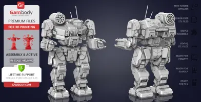
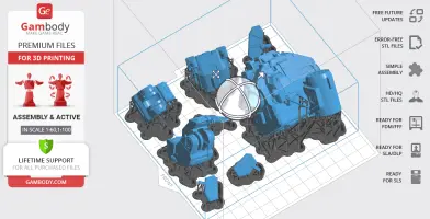
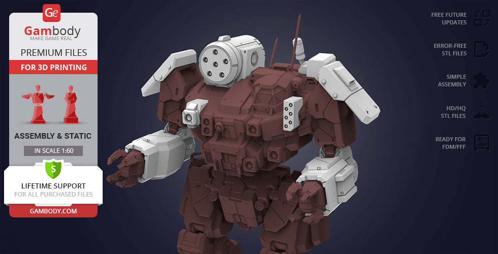
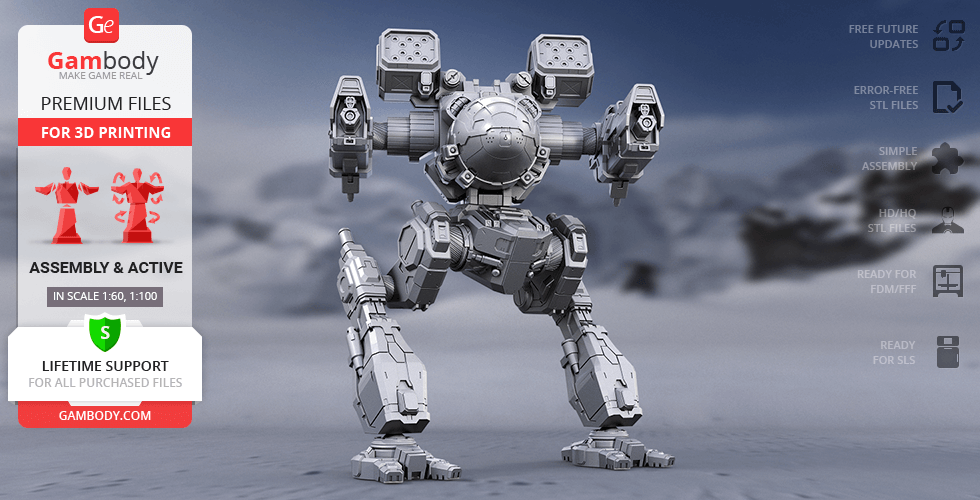
MWO Thunderbolt 3D Printing Model comes in 2 versions for each 3D printer type (FFF/FDM, DLP/SLA/SLS). Files for each version are available for download after the purchase.
Detailed information about this model is available in the DESCRIPTION section.
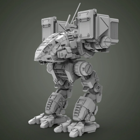
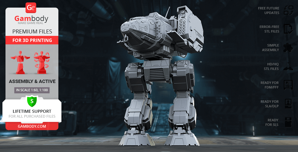
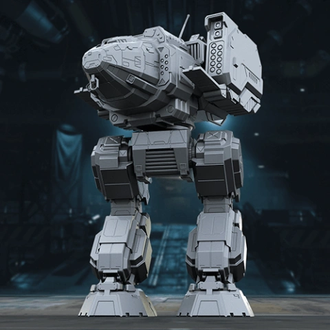
HISTORY OF THE THUNDERBOLT
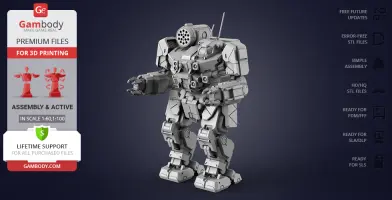
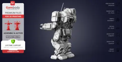
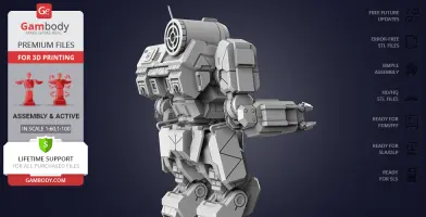
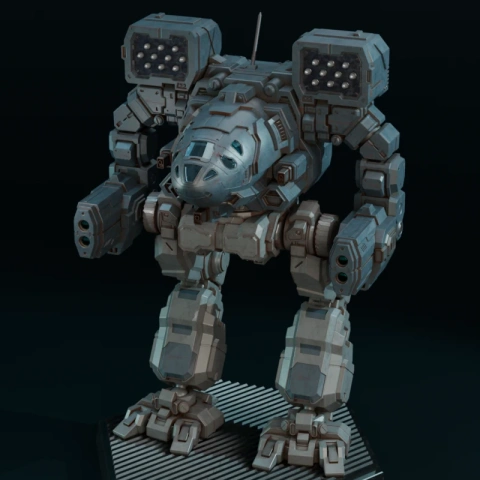
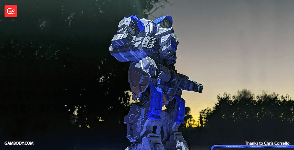
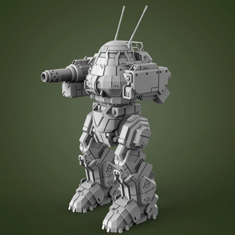
The Thunderbolt started production in 2491 as a planetary-assault mech, and in fact was one of the heaviest mechs produced at that time. Since then the mech, also known as T-Bolt, may have had its classification changed, as larger mechs were built, but thanks to periodic updates it is still feared and respected by many. With its varied arsenal, the Thunderbolt remains one of the best-armed mechs, making it capable of serving in many capacities. It is also an incredibly well-armored mech, rivaling or exceeding the amount of armor carried by some assault mechs. The biggest downside to the Thunderbolt though is poor heat management.
Technical specifications
- Mass - 65 tons
- Chassis - Earthwerk TDR
- Armor - Ryerson 150
- Engine - Magna 260
- Communications System - Neil 8000
- Targeting Tracking System - RCA Instatrac Mark X
- Heat Sinks - 15
- Speed - 64.8 km/h
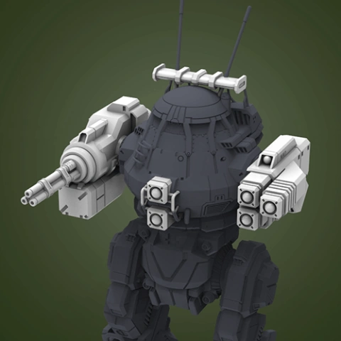
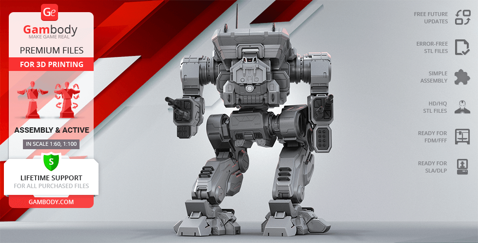
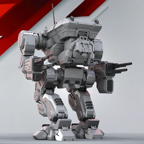
- Armament
- 1x Large Laser
- 1x LRM-15
- 3x Medium Lasers
- 1x SRM-2
- 2x Machine Guns
The basis for the creation was a configuration TDR-5S.
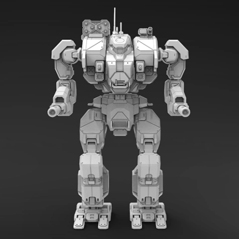
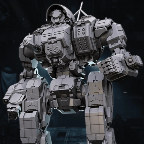
ABOUT THIS 3D MODEL
The model is saved in STL files, a format supported by most 3D printers.
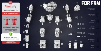
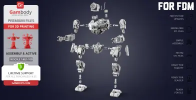
FDM version features:
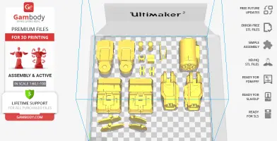
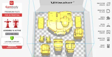
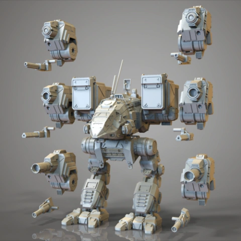
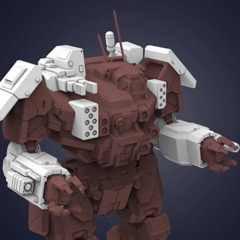
- Contain 28 parts;
- Made with Joints and Claws. One part of Joint (8_Axis_2_A_Joint_(x4)) you need to print 4 times. One part of Joint (19_Axis_1_A_Joint_(x2)) you need to print twice. One part of Claw (9_A_Claw_(x6)) you need to print 6 times.
- Made with Locks. One part of Lock (3_Ge_lock_10H_(x12)) you need to print 12 times.
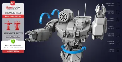
- All limbs are movable as in the game: legs, weapons and torso rotating 360 °
- All parts are divided in such way that you will print them with the smallest amount of supports.
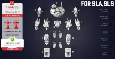
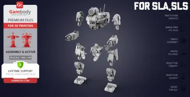
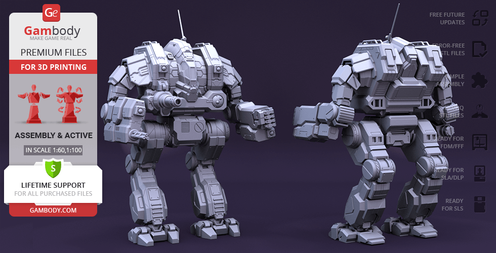
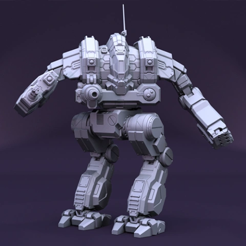
DLP/SLA/SLS version features:
- Same as FDM but smaller, also made as 16 parts;
All STL files for 3D printing have been checked in Netfabb and no errors were shown.
Note: Before starting 3D printing the model, read the Printing Details for CURA 3.4.1. or Simplify3D Software.
There are 28 parts for FFF/FDM version, 16 parts for DLP/SLA/SLS.
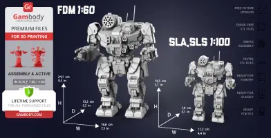
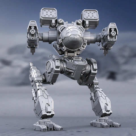
Scale: MWO Thunderbolt height is 14500 mm. The scale of this model made 1/60 for FFF/FDM version and 1/100 for DLP/SLA/SLS version.
FFF/FDM version dimensions:
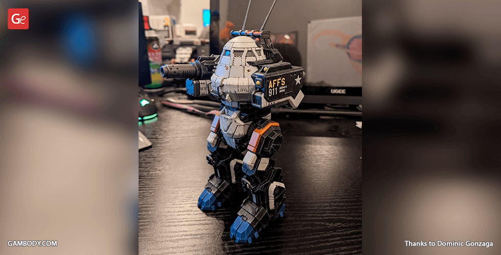
After being printed will stand - 241 mm tall, 186 mm wide, 132 mm deep - with weapon;
SLA/DLP/SLS version dimensions:
After being printed will stand - 145 mm tall, 112 mm wide, 79 mm deep - with weapon;
- Has a few details, to keep printing costs down.
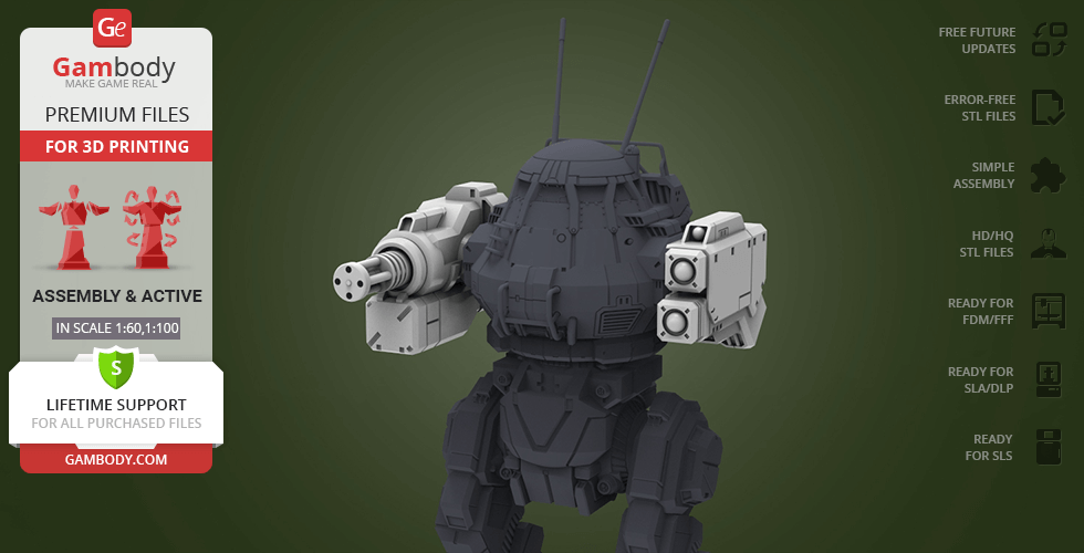
WHAT WILL YOU GET AFTER PURCHASE?
- STL files of MWO Thunderbolt 3D Model for 3D printing which consist of 44 parts;
- 2 versions of files for this model for FFF/FDM, DLP/SLA/SLS;
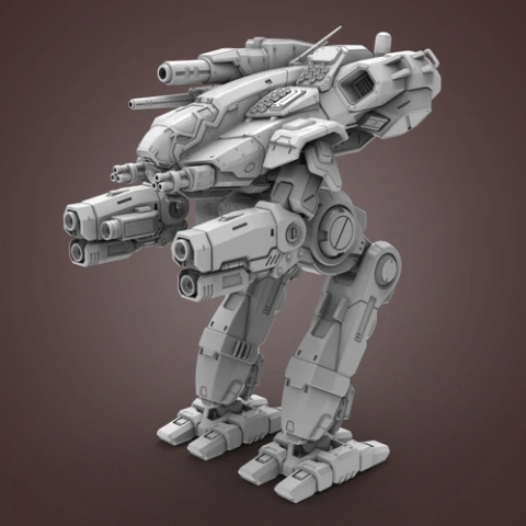
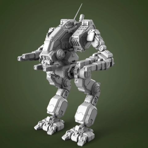
- High-poly detailed model of MWO Thunderbolt;
- Detailed settings that we provide for Cura 3.4.1. and Simplify3D for the best print;
- Full technical support from the Gambody Support Team.
You can get Model of MWO Thunderbolt for 3D Printing right now! Just click the green Buy button in the top-right corner of the model’s page. You can pay with PayPal or your credit card.
Watch the tutorial on how to assemble MWO Thunderbolt 3D Printing Model at Gambody YouTube channel.
Also, you may like other Mechs 3D Printing Models.
_______
FAQ:
Where can I print a model if I have no printer?
How to get started with 3D printing?
How to set up my 3D printer?
How to choose right 3D model print bed positioning?
How to paint printed figurine?
Generic
This model was tested in Cura 3.4.1 and printed on an Ultimaker 2 in PLA material. Below you can find printing recommendations for Cura and Simplify3D softwares.
Recommendations: All parts of connectors you need to print with 100% infill.
To avoid printing problems, we recommend the following settings:
Quality
Layer Height: 0.1 mm
Initial Layer Height: 0.3 mm
Line Width: 0.4 mm
Wall Line Width: 0.4 mm
Outer Wall Line Width: 0.4 mm
Inner Wall(s) Line Width: 0.4 mm
Top/Bottom Line Width: 0.4 mm
Infill Line Width: 0.4 mm
Skirt/Brim Line Width: 0.4 mm
Support Line Width: 0.4 mm
Initial Layer Line Width: 100%
Shell
Wall Thickness: 0.8 mm
Wall Line Count: 2
Outer Wall Wipe Distance: 0.2 mm
Top Surface Skin Layers: 0
Top/Bottom Thickness: 0.8 mm
Top Thickness: 0.8 mm
Top Layers: 8
Bottom Thickness: 0.8 mm
Bottom Layers: 8
Top/Bottom Pattern: Lines
Bottom Pattern Initial Layer: Lines
Top/Bottom Line Directions: [ ]
Outer Wall Inset: 0 mm
Compensate Wall Overlaps: Check
Compensate Outer Wall Overlaps: Check
Compensate Inner Wall Overlaps: Check
Fill Gaps Between Walls: Everywhere
Filter Out Tiny Gaps: Check
Horizontal Expansion: 0 mm
Initial Layer Horizontal Expansion: 0 mm
Z Seam Alignment: Sharpest Corner
Seam Corner Preference: Hide Seam
Ignore Small Z Gaps: Check
Extra Skin Wall Count: 1
Infill
Infill Density: 20% (100% for all parts of connectors)
Infill Line Distance: 4.0 mm
Infill Pattern: Grid
Infill Line Directions: [ ]
Infill X Offset: 0 mm
Infill Y Offset: 0 mm
Infill Overlap Percentage: 10%
Infill Overlap: 0.04 mm
Skin Overlap Percentage: 5%
Skin Overlap: 0.02 mm
Infill Wipe Distance: 0.1 mm
Infill Layer Thickness: 0.1 mm
Gradual Infill Steps: 1
Gradual Infill Steps Height: 1.5 mm
Infill Before Walls: Check
Minimum Infill Area: 0 mm2
Skin Removal Width: 0.8 mm
Top Skin Removal Width: 0.8 mm
Bottom Skin Removal Width: 0.8 mm
Skin Expand Distance: 0.8
Top Skin Expand Distance: 0.8
Bottom Skin Expand Distance: 0.8
Maximum Skin Angle for Expansion: 90˚
Minimum Skin Width for Expansion: 0.0
Material
Initial Layer Flow: 100%
Enable Retraction: Check
Retraction Extra Prime Amount: 0 mm3
Retraction Minimum Travel: 0.8 mm
Maximum Retraction Count: 90
Minimum Extrusion Distance Window: 6.5 mm
Nozzle Switch Retraction Distance: 16 mm
Nozzle Switch Retraction Speed: 20 mm/s
Nozzle Switch Retract Speed: 20 mm/s
Nozzle Switch Prime Speed: 20 mm/s
Speed
Print Speed: 45 mm/s
Infill Speed: 50 mm/s
Wall Speed: 22.5 mm/s
Outer Wall Speed: 22.5 mm/s
Inner Wall Speed: 45 mm/s
Top/Bottom Speed: 15 mm/s
Support Speed: 45 mm/s
Support Infill Speed: 45 mm/s
Travel Speed: 60 mm/s
Initial Layer Speed: 22.5 mm/s
Initial Layer Print Speed: 22.5 mm/s
Initial Layer Travel Speed: 30 mm/s
Skirt/Brim Speed: 30 mm/s
Maximum Z Speed: 0 mm/s
Number of Slower Layers: 2
Travel
Combing Mode: All
Avoid Printed Parts when Traveling: Check
Travel Avoid Distance: 0.6562 mm
Layer Start X: 0.0 mm
Layer Start Y: 0.0 mm
Cooling
Enable Print Cooling: Check
Fan Speed: 100%
Regular Fan Speed: 100%
Maximum Fan Speed: 100%
Regular/Maximum Fan Speed Threshold: 10 s
Initial Fan Speed: 0%
Regular Fan Speed at Height: 0.3 mm
Regular Fan Speed at Layer: 2
Minimum Layer Time: 5 s
Minimum Speed: 10 mm/s
Support
Generate Support: Check
Support Placement: Everywhere
Support Overhang Angle: 50°
Support Pattern: Zig Zag
Connect Support ZigZags: Check
Support Density: 15 %
Support Line Distance: 1.3333 mm
Support Z Distance: 0.3 mm
Support Top Distance: 0.3 mm
Support Bottom Distance: 0.3 mm
Support X/Y Distance: 1 mm
Support Distance Priority: Z overrides X/Y
Minimum Support X/Y Distance: 0.25 mm
Support Stair Step Height: 0.3 mm
Support Stair Step Maximum Width: 5.0 mm
Support Join Distance: 2.0 mm
Support Horizontal Expansion: 0.2 mm
Support Infill Layer Thickness: 0.1 mm
Gradual Support Infill Steps: 0
Use Towers: Check
Tower Diameter: 3.0 mm
Minimum Diameter: 3.0 mm
Tower Roof Angle: 65°
Build Plate Adhesion
Build Plate Adhesion Type: Brim
Skirt/Brim Minimum Length: 250 mm
Brim Width: 8.0 mm
Brim Line Count: 18
Brim Only on Outside: Check
Mesh Fixes
Union Overlapping Volumes: Check
Merged Meshes Overlap: 0.15 mm
Special Modes
Print Sequence: All at Once
Surface Mode: Normal
Experimental
Slicing Tolerance: Middle
Maximum Resolution: 0.01 mm
Flow rate compensation max extrusion offset: 0 mm
Flow rate compensation factor: 100%
Disclaimer: This model will look outstanding if printed on SLA/SLS 3D printer. The accuracy of the model printed on FFF printer can vary from the result shown in the pictures.
This model was tested with PLA material.
To avoid printing problems, we recommend the following settings:
Extruder
Nozzle Diameter: 0.4 mm
Extrusion Multiplier: 0.97
Extrusion Width: Auto
Retraction Distance: 5.00 mm
Extra Restart Distance: 0.00 mm
Retraction Vertical Lift: 0.08 mm
Retraction Speed: 5400.0 mm/min
Wipe Distance: 5.00 mm
Layer
Primary Layer Height: 0.2 mm
Top Solid Layers: 8
Bottom Solid Layers: 5
Outline/Perimeter Shells: 2
Outline Direction: Inside-Out
First Layer Height: 90%
First Layer Width: 100%
First Layer Speed: 20%
Additions
Use Skirt/Brim: Check
Skirt Layers: 1
Skirt Offset from Part: 6.00 mm
Skirt Outlines: 5
Infill
Internal Fill Pattern: Fast Honeycomb
External Fill Patern: Rectilinear
Interior Fill Percentage: 10%
Outline Overlap: 22%
Infill Extrusion Width: 100%
Minimum Infill Length: 5.00 mm
Combine Infill Every: 1 layers
External Infill Angle Offsets: 45/-45 deg
Support
Generate Support Material: Check
Support Infill Percentage: 15%
Extra Inflation Distance: 1.00 mm
Support Base Layers: 0
Combine Support Every: 1 layers
Dense Support Layers: 0
Dense Infill Percentage: 70%
Support Type: Normal
Support Pillar Resolution: 5.00 mm
Max Overhang Angle: 60 deg
Horizontal Offset From Part: 0.50 mm
Upper Vertical Separation Layers: 1
Lower Vertical Separation Layers: 1
Support Infill Angles: 45 deg
Temperature
Extruder 1 Temperature: 210
Heated Bed: 60
Cooling
Increase fan speed for layers below: 45.0 sec
Maximum Cooling fan speed: 50%
Bridging fan speed override: 100%
Speeds
Default Printing Speed: 4800.0 mm/min
Outline Underspeed: 50%
Solid Infill Underspeed: 80%
Support Structure Underspeed: 80%
X/Y Axis Movement Speed: 10800.0 mm/min
Z Axis Movemen Speed: 1002.0 mm/min
Adjust printing speed for layers below: 15.0 sec
Allow speed reduction down to: 20%
Other
Unsupported area threshold: 20.0 sq m


Comments